111-F00 Page 11/16
MAINTENANCE:
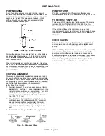
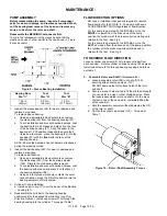
PUSHROD INSTALLATION
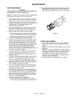
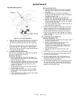
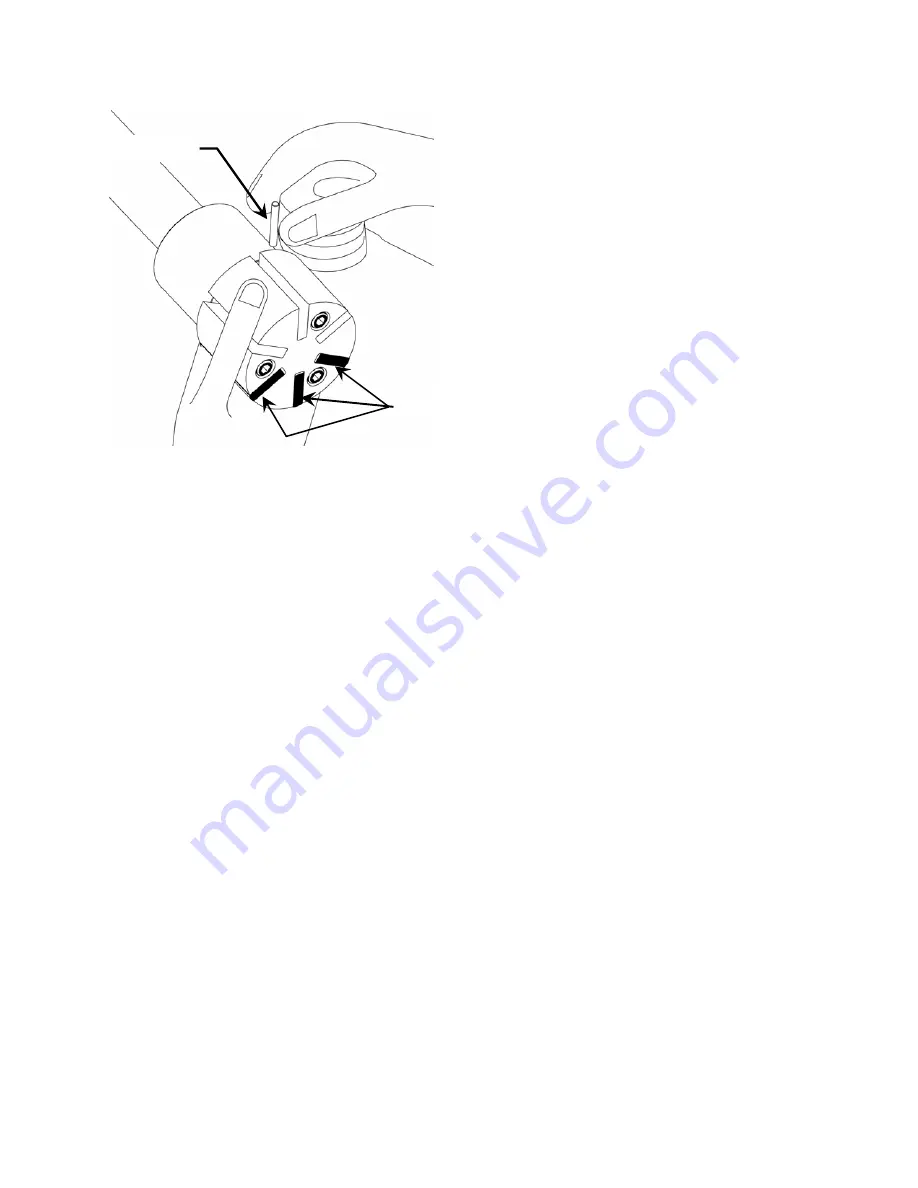
Figure 11 – Pushrod Installation
6. Insert the vanes into the bottom three rotor slots with the
relief grooves facing in the direction of pump rotation,
and with the rounded edges outward. See Figures 6 &
11.
7. Hold the three bottom vanes in place while inserting the
three push rods (77). See Figure 11. Note: A small
amount of grease may be used to help hold the pushrod
in the rotor during assembly.
8. Installing Seal Rotating Elements
Refer to the seal manufacturer’s instructions for detailed
removal and replacement instructions.
Mechanical Seal type 9
a. Apply a small amount of Flowserve Pac-Ease™ or
equivalent water based lubricant on the shaft between
the shaft end and the rotor
b. Slide the seal rotating assembly (153B) over the shaft
with the rotating face away from the rotor until contact
is made with the large diameter of the shaft. Seal
spacer is not needed.
c. Tighten set screws and remove seal spacer clips per
manufacturer’s directions.
d. After the bottom vanes and push rods are installed,
carefully insert the driven end of rotor and shaft into
the cylinder.
e. Clean the polished face of the seal with a clean tissue
and alcohol before reassembly.
Mechanical Seal Type 16
a. After the bottom vanes and push rods are installed,
carefully insert the driven end of rotor and shaft into
the cylinder.
b. Apply a small amount of Flowserve Pac-Ease™ or
equivalent water based lubricant on the shaft between
the shaft end and the rotor.
c. Install the seal spacer (82) over the shaft until it
bottoms out on the large diameter of the shaft.
d. Slide the seal rotating assembly (153B) over the shaft
with the rotating face away from the rotor until contact
is made with the seal spacer.
e. Clean the polished face of the seal with a clean tissue
and alcohol before reassembly.
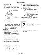
9. Install the remaining vanes by rotating the shaft until an
empty vane slot is in the 12 o’clock position, ensuring
that the rounded edge is UP, and the relief grooves are
facing towards the direction of rotation. See Figure 6.
Repeat until all vanes have been installed. This method
of vane installation ensures the push rods do not fall out
of their rotor slots.
10. Install Stationary Seal Elements
Mechanical Seal type 9, 16
a. Apply a small amount of lubricant in the seal access of
the bearing adjuster (188).
b. Install a new stationary seat and O-ring into the
bearing adjuster until fully bottomed out.
Type 9 only - align slot in stationary seat with anti-
rotation pin (25A) in bearing adjuster (188) before
inserting stationary seat.
c. Clean the polished face with a clean tissue and
alcohol.
11. Install a new O-ring (51) onto the bearing adjuster (188)
12. Lubricate the O-ring seal area on the bearing housing
(57) with a light coating of oil.
13. Start the bearing adjuster (188) (with stationary seal
elements installed) over the shaft, being careful not to
damage the seal with the shaft end.
14. Screw the bearing adjuster (188) to the bearing housing
(57) until they are flush. Be sure that the 2 setscrews
(189) are not interfering with the flush fit of the bearing
adjuster to the bearing housing.
PUSHROD
VANES
Содержание 111-F01
Страница 15: ...111 F00 Page 15 16 NOTES...


