


5
2MP 12X PTZ HD-SDI/HDcctv Dome Camera
SECTION 2: INSTALLATION
2.
Drill holes in the mounting surface for the wall anchors (if used) or mounting bolts.
—
If the network cables will be routed into the mounting bracket where it attaches to the wall, drill an appropriate hole
for the network cables.
3.
Attach the mounting bracket securely to the mounting surface using appropriate mounting hardware.
4.
If conduit will be used to shield the network cables, install the conduit and attached it to the mounting bracket.
5.
Remove the cable access cover from the mounting bracket.
6.
Route the network cables (RS-485, alarm in/out, HD-SDI video, 24 Vac power leads) into the mounting bracket.
2.3 Set the camera hardware configuration switches
The camera hardware configuration switches are located inside the camera module. These configuration switches set the camera
device ID, video mode (NTSC or PAL), and RS-485 protocol, baud rate, and termination state.
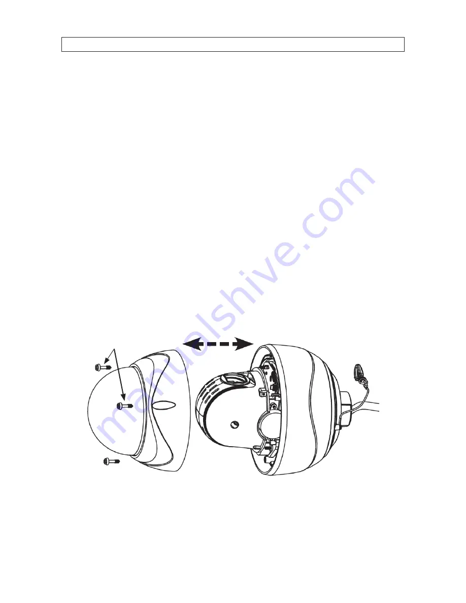
1.
Remove the camera module from the packaging and place it on a flat, clean surface.
2.
Remove the three screws securing the dome cover and set it apart from the camera module. Note that the dome cover is
connected to the camera module with a retaining cable (not shown below).
Camera module
Safety cable
Drop
cable
Dome
cover
Dome cover screws
3.
Set the hardware configuration switches as required for your installation. Switch functions are described below.
Содержание BLK-HDPTZ12
Страница 6: ...vi NOTES ...
Страница 44: ...38 SECTION 4 OSD MENU STRUCTURE REFERENCE 4 2 DISPLAY SETUP submenus ...
Страница 45: ...39 2MP 12X PTZ HD SDI HDcctv Dome Camera SECTION 4 OSD MENU STRUCTURE REFERENCE 4 3 DOME MOTION SETUP submenus ...
Страница 46: ...40 SECTION 4 OSD MENU STRUCTURE REFERENCE 4 4 Miscellaneous submenus 4 5 SYSTEM SETUP submenus ...
Страница 52: ...46 ...


