17
CHAPTER 4: Installation
To modify the DCE/DTE orientation from the default position (DCE), you must
open the X.21 Line Driver’s case.
4.3.2 O
PENING THE
C
ASE
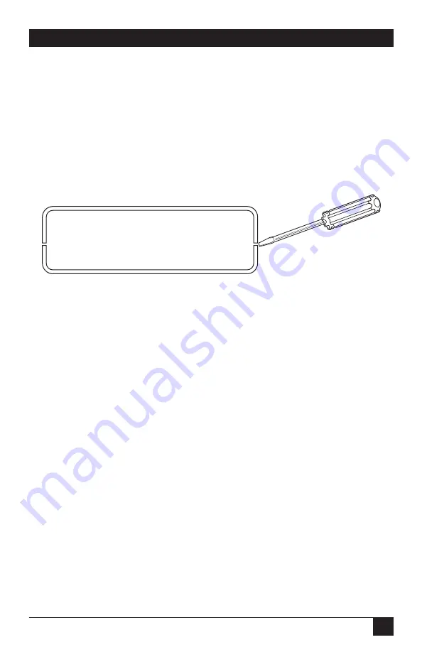
To open the Line Driver’s case, insert a flat-head screwdriver into an open slot on
both sides of the case, as in Figure 4-5. Twist the screwdriver head slightly, and the
top half of the case will separate from the lower half (see Figure 4-5). Take caution
not to damage of the PC-board mounted components.
Figure 4-5. Opening the case with a small screwdriver.
The DCE/DTE strap is located on the top side of the Line Driver’s PC board (see
Figure 4-6). The arrows on the top of the strap indicate the configuration of the
X.21 port (for example, if the DCE arrows are pointing toward the DB15
connector, the X.21 port is wired as a DCE). Change the DCE/DTE orientation by
pulling the strap out of its socket, rotating it 180º, then plugging the strap back
into the socket. You will see that the DCE/DTE arrows now point in the opposite
directions, showing the new configuration of the X.21 port. To close the case, fit
the two halves together snugly and snap them back in place.


