background image

724-746-5500   |   blackbox.com 

Page 6


ServView V KVM Tray

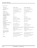
1. Specifications

  Specification 

KVT517A models 

KVT517A-WIDE model

  Active Display Area:  

10.6"H x 13.3"W (27 x 33.8 cm) 

9"H x 14.5"W (22.9 x 36.7 cm)

  Approvals:


CE, FCC for the product; UL

®

, TUV,  

CE, FCC for the product; UL

®

, TUV,  


CE for power supply 

CE for power supply

  Backlight Unit:


4 CCFLs edge-light (top/bottom) 

4 CCFLs edge-light (top/bottom)

  Brightness (cd/m^2):


300 (center) 

400 center

  Contrast Ratio (Typical):


800:1 

500:1

  Display Color (RGB 6-bits  


+ FRC data):


16.2 M 

16.2 M

  Display Mode:


Normally white 

Normally white

  Input Signal:


RGB analog, H/V separate 

RGB analog, H/V separate

  Pixel Pitch:


0.264 mm (H) x 0.264 mm (V) 

0.191 mm (H) x 0.190 mm (V)

  Plug-n-Play VESA:


VESA DDC 1/2B 

VESA DDC 1/2B

  Resolution:  

1280 x 1024 @ 60/70/75 Hz 

1920 x 1080P


VGA Resolution for Optimum 

  Performance:


1280 x 1024 @60 Hz 

1920 x 1080P

'

  Viewing Angle (Typical):


-80 to +80 (H), -80 to +80 

-70 to +70 (H), -60 to +60

  Connectors:


(1) Centronics

®

 female 

(1) Centronics female

  Temperature:


Operating: +32 to +122° F (0 to +50° C);   Operating: +32 to +122° F (0 to +50° C);  


Storage: -4 to +140° F (-20 to +60° C) 

Storage: -4 to +140° F (-20 to +60° C)

  Humidity (Relative):  

Operating: 8–95%;  

Operating: 8–95%; 


Storage: Less than or equal to 95% 

Storage: Less than or equal to 95%

  Power Consumption  

37 watts 

13.6 watts 


(Maximum, Typical):

  Power:  

12 VDC (from external 100–240-VAC  

12 VDC (from external 100–240-VAC 


power adapter), 47–63 Hz 

power adapter), 47–63 Hz

  Size:  

1.75"H (1U) x 17"W x 19.5" to 39.5"D 

1.75"H (1U) x 17"W x 19.5" to 39.5"D


(4.4 x 43.2 x 49.5 to 100.3 cm) 

(4.4 x 43.2 x 49.5 to 100.3 cm)


Weight:


23 lb. (10.4 kg) 

23 lb. (10.4 kg)

Содержание KVT517A-16PV

Страница 1: ...VT517A 16PV KVT517A 8PV KVT517A 16UV KVT517A 8UV KVT517A 8DV WIDE Order toll free in the U S Call 877 877 BBOX outside U S call 724 746 5500 FREE technical support 24 hours a day 7 days a week Call 72...

Страница 2: ...ess than 20 seconds Trademarks Used in This Manual Black Box and the Double Diamond logo are registered trademarks and ServView and ServSwitch are trademarks of BB Technologies Inc Centronics is a reg...

Страница 3: ...ent is operated in a commercial environment Operation of this equipment in a residential area is likely to cause interference in which case the user at his own expense will be required to take whateve...

Страница 4: ...idan el flujo de aire por los orificios de ventilaci n 10 El equipo el ctrico deber ser situado fuera del alcance de fuentes de calor como radiadores registros de calor estufas u otros aparatos incluy...

Страница 5: ...ontrol and Status LEDs 19 4 2 Extra Keyboard and Mouse Control 21 4 3 Opening and Closing the Console 22 4 3 1 Opening the Console 22 4 3 2 Closing the Console 24 4 3 3 Opening the Keyboard Touch Pad...

Страница 6: ...Plug n Play VESA VESA DDC 1 2B VESA DDC 1 2B Resolution 1280 x 1024 60 70 75 Hz 1920 x 1080P VGA Resolution for Optimum Performance 1280 x 1024 60 Hz 1920 x 1080P Viewing Angle Typical 80 to 80 H 80...

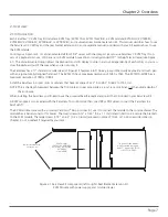
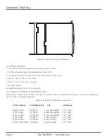
Страница 7: ...as a maximum resolution of 1920 x 1080P Install the ServView in 4 post racks or cabinets that have rail space of 23 7 D to 45 3 D 60 2 to 115 1 cm NOTE This is the depth measured between the front pol...

Страница 8: ...or 10 32 nuts bolts 2 3 ServView V KVM Tray Kit Part Numbers The ServView V KVM Tray Kit includes a ServView V KVM Tray a PS 2 or USB KVM module and a universal rear bracket exten sion kit Table 2 1 l...

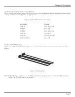
Страница 9: ...rface KVT4S1UV 1 port PS 2 or USB KVT4S8PV 8 port PS 2 KVT4S8UV 8 port PS 2 or USB KVT4S16PV 16 port PS 2 KVT4S16UV 16 port PS 2 or USB KVT517A 8DV WIDE 8 port USB 2 5 Rear Bracket Extensions Figure 2...

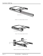
Страница 10: ...ServView V KVM Tray 45 3 115 1 cm Figure 2 4 The maximum depth of the unit 23 7 60 2 cm Figure 2 5 The minimum depth of the unit Open rack post 1 Open rack post 2 ServView V Tray Figure 2 6 ServView...

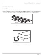
Страница 11: ...crews included attach the extensions included with your ServView V Kit to both sides of the KVM switch module See Figures 3 1 through 3 5 The wide edged plastic extension should be on the top side see...

Страница 12: ...age 12 ServView V KVM Tray Extension Switch module Figure 3 3 Attaching the extensions to one side of the KVM switch module Extension on side of switch module Switch module Figure 3 4 KVM switch modul...

Страница 13: ...view of module with extensions attached 3 Using four cabinet screws included screw the unit onto the rack See Figures 3 6 and 3 7 WARNING Do not remove the safety stopper until you complete the assemb...

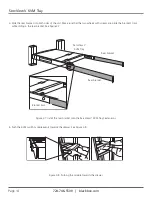
Страница 14: ...crews are inside the bracket s track while sliding in the rear bracket See Figure 3 7 ServView V KVM Tray Rear bracket Rear bracket Bracket track Figure 3 7 Install the rear bracket onto the ServView...

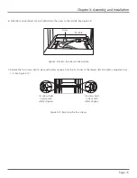
Страница 15: ...9 Screw Module Figure 3 9 Fasten the screw to the module 7 Remove the four screws held in place with safety stoppers from the front sides of the drawer left and right in sequence from 1 4 See Figure...

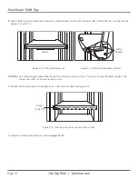
Страница 16: ...Sliding the drawer out Figure 3 12 Removing the safety stoppers WARNING The safety stoppers prevent the drawer from sliding out when in transit Once you remove the safety stoppers the drawer may slide...

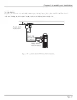
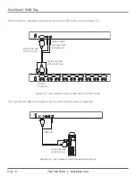
Страница 17: ...odule in the ServView V refer to the user s manual for that module The 1 port PS 2 and USB switch module connects to a PS 2 console as shown in Figure 3 14 Male to Female HD15 for VGA Male to Male 6 P...

Страница 18: ...Female HD15 for Mouse Male to Female HD15 for VGA Male to Male 6 Pin Mini DIN for Keyboard Console Connectors Figure 3 15 1 port module and 8 port KVM switch with PS 2 console The 1 port PS 2 and USB...

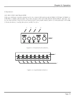
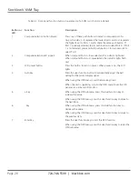
Страница 19: ...V is installed in the ServView V Tray It does not apply to the 1 port KVM switch module KVT4S1UV Figures 4 1 and 4 2 show the ServView V Tray s LCD monitor function buttons and computer selection butt...

Страница 20: ...H are selected the indicator lights flash red 3 LCD power button Press this button to turn on power When power is on the LCD lights 4 Auto key Press this dual function button to automatically adjust t...

Страница 21: ...in Figure 4 3 Via a slide switch choose wireless keyboard and mouse combination or wireless mouse only for a keyboard mouse transceiver Touch pad function disabled Scroll function disabled enabled Fi...

Страница 22: ...led out This may cause personal injury and or property damage Do not put your fingers hands or anything else on the rear cabinet Do not touch any part behind the rear cabinet Keep the area behind the...

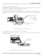
Страница 23: ...ee Figure 4 6 Keyboard touch pad LCD monitor Figure 4 6 Lift out the LCD panel Opening LCD Monitor Only 1 Holding the LCD monitor s handle pull it upwards See Figure 4 7 Figure 4 7 Opening the LCD mon...

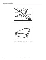
Страница 24: ...ack slowly and evenly See Figure 4 8 Metal plate Metal plate Figure 4 8 Closing the console CAUTION When the LCD monitor is pulled out all the way you will see both edges of two metal unlock plates ex...

Страница 25: ...t the keyboard s upper cover on the ends of the left and right sides See Figure 4 9 2 screws and brackets 2 screws and brackets Figure 4 9 Screws on the keyboard touch pad and LCD monitor assembly 2 U...

Страница 26: ...ll the keyboard out to the end and unfold the LCD monitor See Figure 4 11 Figure 4 11 Unfold monitor 2 There is a round hole under the drawer Using a finger push the keyboard up and through the hole S...

Страница 27: ...3 Double check that the USB cable is placed inside the tray without any twist 4 Plug in the keyboard connector firmly See Figures 4 13 through 4 17 WARNING Make sure you place the USB cable inside th...

Страница 28: ...724 746 5500 blackbox com Page 28 ServView V KVM Tray Figure 4 15 Correct way to replace the keyboard diagram 2 Figure 4 16 Wrong way to replace the keyboard diagram 2...

Страница 29: ...riangular mark on the mini USB connector faces outwards 4 4 3 Alternate Way to Fasten the Keyboard Recommended 1 Pull the keyboard out as shown in Figure 4 5 2 Use the included six tapping screws to f...

Страница 30: ...es a wheel mouse When touching this area you will see two small triangular marks this is the simulated wheel See Figure 4 19 Touch pad Simulated wheel Figure 4 19 Touch pad showing simulated mouse are...

Страница 31: ...e touch pad attaches to the tray via a mini USB cable To replace the touch pad adjust the length of the mini USB cable and slide the touch pad all the way in until you hear a clicking sound that indic...

Страница 32: ...assistance if you have a complete description including the nature and duration of the problem when the problem occurs the components involved in the problem any particular application that when used...

Страница 33: ...nets and racks and power and surge protection products to media converters and Ethernet switches all supported by free live 24 7 Tech support available in 20 seconds or less Copyright 2010 Black Box C...

Отзывы: