


724-746-5500 | blackbox.com
ServSwitch Universal Extender
20
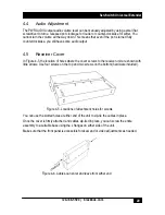
Figure 4-5. Locations of attachment holes for screws
4.4 Audio
Adjustment
The PWR AUDIO output audio volume level can be manually adjusted by using a small flat
screwdriver to turn a recessed pot clockwise for louder or counter-clockwise for softer. You
cannot turn the volume all the way down. This means that even if the pot is turned fully
counterclockwise, you still have some audio output.
4.5 Receiver
Cover
In Figure 4-5, the location of holes where the cover screws to the receiver unit are shown with
little arrows. Use four screws on the top and two screws on the bottom (hardware included).
You can use the slotted holes at either end of the unit to zip-tie the cables in place.
Once the cover is firmly attached and cables zip-tied in place, you can screw the entire
assembly to a suitable base using the L flanges on either side of the unit.
Make sure that the front panel is accessible for skew and or video adjustments as needed.
Figure 4-6. Cables can enter and leave from either end


