


724-746-5500 | blackbox.com
ServSwitch Universal Extender
10
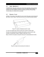
2.4.2 Receiver Unit
Figure 2.3 shows the receiver unit’s front panel. Table 2-3 describes its components.
TABLE 2-3
Number
Component
Description
1,2,3 (Top Row)
1,2,3 (Bottom Row)
LED’s
Link LED’s light when communication between sender and receiver
is established.
Data LED’s light when valid data is being sent form the PC to the
sender.
4
Channel
Select Push
Button
Select A or B for skew compensation
5
Volume
Control
Adjust Volume
6
Up/Down
Push Buttons
Toggle up/down to adjust skew
7
Red LED
Lights when adjusting “RED” skew compensation
8
Green LED
Lights when adjusting “GREEN” skew compensation
9
Blue LED
Lights when adjusting “BLUE” skew compensation
10
Select Button
Use to select RGB skew compensation
11
Power LED
Lights when power is on
4
10
1 2 3
5
7 8 9
11
6
Figure 2.3 Receiver unit’s front panel


