Installation
7
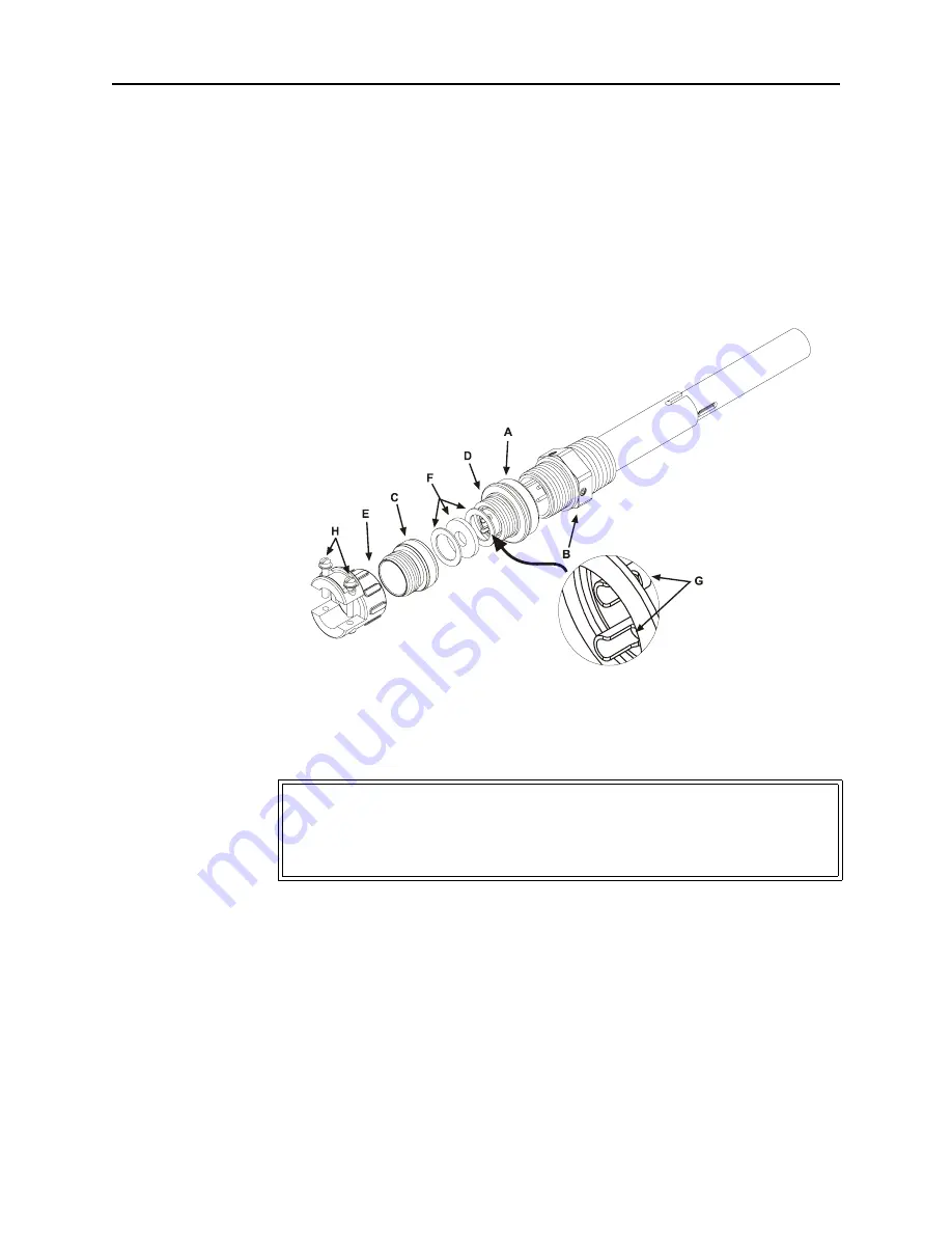
6. Securely solder the control switch leads to the lugs (G) of the connector base.
Note:
The ring-nut (A) must be in place over the base plug (D) with
the knurled end facing out.
7. Screw on the cover ring, then fasten the cable clamp (E) in place and
tighten both yoke screws (H).
8. Put the plug back on the thermoswitch and tighten the nut (A).
Figure 4 Thermoswitch Assembly
Connecting RF Power
After installing the load, the RF transmission line can be attached using stan-
dard coaxial line coupling kits.
Using a “QC” Connector Coupling
Use 50 ohm coaxial cable such as RG-218/U or -220/U (-17A or -19A), appro-
priate for the frequency and power level of operation. Use a cable connector
which will mate with the one on the load.
Using a 13-30 Coupling
Use 50 ohm coaxial cable such as RG-8A/U, RG-9U, RG-213/U, or equivalent
with a male 13-30 plug.
WARNING
Never attempt to connect or disconnect RF equipment from the
transmission line while RF power is being applied. Leaking RF energy is a
potential health hazard.
深圳市新朗普电子科技有限公司
www.xLp17.com Email:[email protected]
TEL:0755-83986300 FAX:0755-88850515
QQ:55178055 285480356
深圳市新朗普电子科技有限公司
www.xLp17.com Email:[email protected]
TEL:0755-83986300 FAX:0755-88850515
QQ:55178055 285480356


