background image

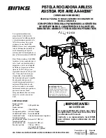
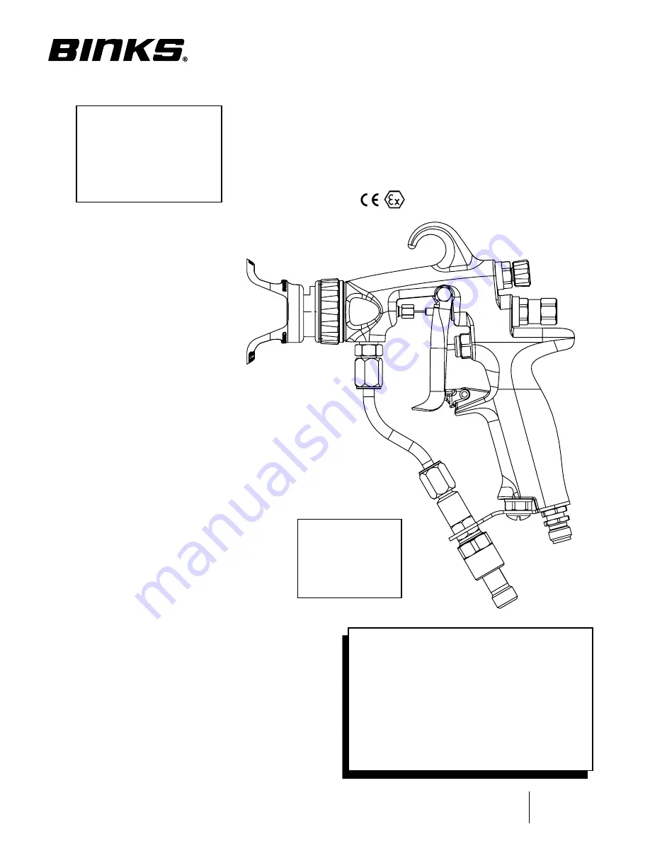
AA4400M

 AIR-AssIst  

AIRLEss spRAy Gun

(0909-4400-XXXXXX)

sEE pAGE 10 foR Gun AssEMbLy pARt nuMbER

(WItH fLAt tIp/tWIst tIp optIon,  

fAn sIZE ADJustMEnt fEAtuRE AnD 

HVLp/tRAns-tECH tECHnoLoGy) 

Part 

Sheet

77-2922R-9-E

The following instructions 
provide the necessary 
information for the proper 
operation and preventive 
maintenance of the Binks 
AA4400M Air-Assist Airless 
Spray Gun. Please read and 
understand all information in this  
document in order to get the 
maximum performance from 
your new AA4400M spray gun.

In the AA4400M spray gun, the 
paint or other material to be 
sprayed is pre-atomized and 
forced through the carbide tip by 
the typical 1,600-3,800 psi fluid 
pressure (with capabilities up to 
4,400 psi/303 bar). As a result of 
the pre-atomizing, the final 
shaping air supplied by the air 
cap produces an exceptionally 
fine and even spray pattern. The 
result of this spray pattern is an 
even finish that lends itself to 
products that need an 
exceptionally fine finish with 
reduced overspray and VOC 
emissions.

Replaces 

Part Sheet 

77-2922R-8-E

II 2 G X

SPEcIfIcatIonS:

Maximum  

Fluid Pressure: 

 4400 psi/303 bar

Maximum  

Air Pressure: 

 100 psi/6.8 bar

Gun Body: 

 Forged Aluminum 

Fluid Path: 

 Stainless Steel

Fluid Seat: 

Tungsten Carbide Seat  

Fluid Inlet Size: 

 1/4" NPS(m) Thread

Air Inlet Size: 

1/4" NPS(m) Thread

Gun Weight: 

 17.28 oz./490 g  

(without Tip, Aircap, Guard)

READ ALL InstRuCtIons bEfoRE opERAtInG tHIs bInKs pRoDuCt

IMpoRtAnt!

Do not DEStRoY

It is the customer's responsibility to have 
all operators and service personnel read 
and understand this manual.

contact your local Binks representative 
for additional copies of this manual.

PRoP 65 WaRnInG
WARNING: This product 
contains chemicals known 
to the State of California 
to cause cancer and birth 
defects or other 
reproductive harm.

English: Pages 1 – 12
Español: Páginas S-1 – S-12
Français: Pages F-1 – F-12
Deutsch: Seiten G-1 – G-12
Italiano: Pagine I-1 – I-12
Polska: Strony P-1 – P-12

Содержание AA4400M

Страница 1: ...ult of this spray pattern is an even finish that lends itself to products that need an exceptionally fine finish with reduced overspray and VOC emissions Replaces Part Sheet 77 2922R 8 E II 2 G X Specifications Maximum Fluid Pressure 4400 psi 303 bar Maximum Air Pressure 100 psi 6 8 bar Gun Body Forged Aluminum Fluid Path Stainless Steel Fluid Seat Tungsten Carbide Seat Fluid Inlet Size 1 4 NPS m ...

Страница 2: ...poor air ventilation open flames or sparks can cause a hazardous condition and result in fire or explosion and cause serious injury FIRE AND EXPLOSION HAZARD Ground the equipment and object being sprayed Provide fresh air ventilation to avoid the build up of flammable fumes from the material being sprayed or from solvent Extinguish all open flames or pilot lights in spray area Electrically disconn...

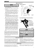
Страница 3: ...rs and similar spraying jobs by developing pressure standardization charts Repeat step 6 until the required mate rial coverage and spraying speed are achieved If the maxi mum fluid pressure is reached before the required material coverage and spraying speed are achieved you may need to switch to a larger fluid tip Typical Hook Up Fan pattern adjustment turn knob counterclockwise to decrease patter...

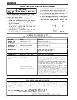
Страница 4: ...BAR Max Dynamic Gun Inlet Air Pressure 14 psi 1 BAR Gun Body Forged Aluminum Alloy Fluid Path Stainless Steel and Tungsten Carbide UHMW Problem Cause Action Fluid leaking from through the seal Worn seal or needle shaft Loose needle seal Replace needle assembly 18 Tighten packing nut gently until leak stops Fluid leaking from the front of the gun Needle ball worn or damaged Worn seat assembly Repla...

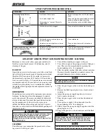
Страница 5: ...d be lubricated after each cleaning The points that need lubrication dur ing the maintenance of air assist airless spray guns include the fluid needle packing and trigger pivot point Gun lube is used to lubricate the fluid needle packing and trigger pivot point CLEANING The following steps summarize the procedure for clean ing air assist airless spray guns 1 Turn off the atomizing air supply to th...

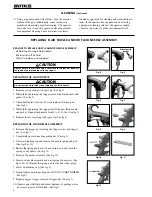
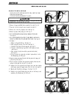
Страница 6: ... the trigger install the new fluid nozzle and gasket Torque fluid nozzle from 9 to 11 ft lbs See fig 5 5 Replace the air cap along with spray tip See fig 4 REPLACING THE FLUID NEEDLE ASSEMBLY 1 Remove the trigger by removing the trigger screw and trigger nut See fig 7 2 Completely unscrew needle packing nut See fig 8 3 Unscrew blanking cap and remove the needle spring and pad See figs 9 10 4 Ensur...

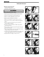
Страница 7: ... through cage bore with slight resistance due to seal e Rear seal must look clean and in position in the bore See fig 18 f If any of the above cannot be rectified replace the air valve See Replacing Air Valve p8 8 Replace spring ensuring the end with the plastic bearing pad goes in first See fig 17 9 Insert air valve assembly into gun and carefully feed over the spring and through the rear seal Se...

Страница 8: ...seal onto Service tool grooves must fit in service tool form See fig 32 8 Push rear seal firmly into hole up to shoulder using Service tool See figs 33 34 9 Insert new spring ensuring the end with the plastic bearing pad goes in first See fig 29 10 Insert air valve assembly into gun and carefully feed over the spring and through the rear seal See fig 35 11 Tighten air valve assembly using fingers ...

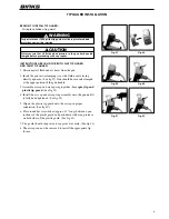
Страница 9: ...he gun until it is fully hand tightened See fig 39 5 Slip on the plastic tip guard onto the air cap in proper orientation See fig 40 6 Place round bar screwdriver approx 12 long between open sections of the plastic guard and push down with even pressure on both sides of the plastic guard See fig 41 7 The guard should snap into air cap groove securely See fig 42 8 The aircap can now be removed to i...

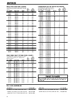
Страница 10: ... 75 TWIST TIP 013 8 0 18 9 513 75 TWIST TIP 013 10 0 18 9 613 75 TWIST TIP 013 12 0 18 9 713 75 TWIST TIP 013 14 0 18 9 215 75 TWIST TIP 015 4 0 24 9 315 75 TWIST TIP 015 6 0 24 9 415 75 TWIST TIP 015 8 0 24 9 515 75 TWIST TIP 015 10 0 24 9 615 75 TWIST TIP 015 12 0 24 9 715 75 TWIST TIP 015 14 0 24 9 217 75 TWIST TIP 017 4 0 31 9 317 75 TWIST TIP 017 6 0 31 9 417 75 TWIST TIP 017 8 0 31 9 517 75 ...

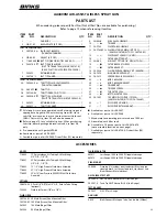
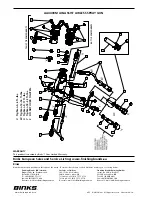
Страница 11: ...tip guard When switching from flat tip to twist tip or vice versa be sure to order correct fluid seat 3 3A For twist tip item 5B will also be needed Refer to page 10 for available tip sizes When purchasing twist tip discard packaged brace seal and use Item 5B only Pre assembled with gasket SPA 98 Available as part of kit 54 5835 Available as part of kit 54 5838 Order Filter 12 separately Available...

Страница 12: ...ibutors throughout the world For technical assistance or the distributor nearest you see listing below Finishing Brands UK Limited Ringwood Road Bournemouth Dorset BH11 9LH UK Tel 44 0 1202 571 111 Fax 44 0 1202 573 488 General e mail info finishingbrands eu Surfaces et Finitions 163 171 Av des Auréats 26014 Valence cedex FR Téléphone 33 0 4 75 75 27 53 Télécopie 33 0 4 75 75 27 79 General e mail ...

Страница 13: ... un patrón de rociado excepcionalmente fino y uniforme El resultado de este patrón de rociado es un acabado uniforme adecuado para productos que necesitan un acabado excepcionalmente fino con menos exceso de rociado y emisiones VOC II 2 G X Especificaciones Presión máxima del fluido 4400 psi 303 bar Presión máxima del aire 100 psi 6 8 bar Cuerpo de la pistola Aluminio forjado Conducto del fluido A...

Страница 14: ...éctricos y de otra índole La puesta a tierra indebida la ventilación insuficiente la llama abierta o las chispas pueden ocasionar condiciones de peligro y producir incendios explosiones y otras lesiones graves PELIGRO DE INCENDIO Y EXPLOSIÓN Conecte a tierra el equipo y el objeto que esté siendo rociado Proporcione ventilación de aire fresco para evitar la acumulación de gases inflamables del mate...

Страница 15: ...e presiones Repita el paso 6 hasta que lograr la cobertura del material y la velocidad de rociado requeridas Si la presión máxima del fluido se logra antes de lograr la cobertura del material y la velocidad de rociado requeridas usted tendría que conseguir una punta de fluido más grande Montaje de la pistola rociadora Bomba Regulador Regulador Aire Aire Aire Fluido Filtro de fluido Pistola Extract...

Страница 16: ...o forjado Conducto del fluido Acero inoxidable y carburo de tungsteno UHMW Problema Causa Solución Filtración de fluido por el sello Sello o eje de la aguja gastados Sello de la aguja flojo Reemplazar el conjunto de la aguja 18 Apretar suavemente la tuerca del empaquetamiento hasta que cese la filtración Filtración de fluido por la parte delantera de la pistola Esfera de la aguja gastada o dañada ...

Страница 17: ...r el regulador del suministro de aire de la bomba en su nivel más bajo en sentido antihorario 7 Colocar el interruptor de seguridad del gatillo de la pistola en la posición desenganchada 8 Encienda el suministro de aire hacia la bomba y cierre la válvula de derivación cebado si la unidad viene equipada con una 9 Ajustar lentamente el regulador del suministro de aire de la bomba hasta que la bomba ...

Страница 18: ...a guarnición Aplicar una torsión de 9 a 11 pies lbs a la boquilla de fluido Ver Fig 5 5 Reemplazar el casquillo de aire junto con la punta de rociado Ver Fig 4 REEMPLAZO DEL CONJUNTO DE LA AGUJA DE FLUIDO 1 Quitar el gatillo sacando el tornillo del disparador y la tuerca del gatillo Ver Fig 7 2 Destornillar completamente la tuerca del empaquetamiento de la aguja Ver Fig 8 3 Destornillar la tapa de...

Страница 19: ...aula con una leve resistencia debida al sello e El sello trasero debe verse limpio y colocado en su lugar en el diámetro interior Ver Fig 18 f Si no se puede rectificar ninguno de los puntos anteriores reemplace la válvula de aire Ver Reemplazo de la válvula de aire en la Pág 8 8 Reemplazar el resorte asegurándose de que el extremo con el soporte del cojinete de plástico vaya primero Ver Fig 17 9 ...

Страница 20: ... herramienta de servicio las muescas deben corresponder a la forma de la herramienta de servicio Ver Fig 32 8 Empujar con firmeza el sello trasero en el orificio hasta el reborde utilizando una herramienta de servicio Ver Fig 33 y 34 9 Insertar el nuevo resorte asegurando que el extremo con el soporte del cojinete de plástico vaya primero Ver Fig 29 10 Insertar el conjunto de la válvula de aire en...

Страница 21: ...o del casquillo de aire hacia la pistola hasta que esté completamente apretada a mano Ver Fig 39 5 Deslice el resguardo plástico de la punta sobre el casquillo de aire con la orientación debida Ver Fig 40 6 Coloque el destornillador de barra redonda aprox 12 de long entre las secciones abiertas del protector plástico y oprima con presión uniforme en ambos lados el protector plástico Ver Fig 41 7 E...

Страница 22: ... 013 10 0 18 9 613 75 PUNTA GIRATORIA 0 013 12 0 18 9 713 75 PUNTA GIRATORIA 0 013 14 0 18 9 215 75 PUNTA GIRATORIA 0 015 4 0 24 9 315 75 PUNTA GIRATORIA 0 015 6 0 24 9 415 75 PUNTA GIRATORIA 0 015 8 0 24 9 515 75 PUNTA GIRATORIA 0 015 10 0 24 9 615 75 PUNTA GIRATORIA 0 015 12 0 24 9 715 75 PUNTA GIRATORIA 0 015 14 0 24 9 217 75 PUNTA GIRATORIA 0 017 4 0 31 9 317 75 PUNTA GIRATORIA 0 017 6 0 31 9 ...

Страница 23: ...piado Al pasar de punta plana a punta giratoria o viceversa asegúrese de pedir el asiento del fluido correcto 3 3A Para la punta giratoria también se necesitará el artículo 5B Consulte la página S 10 para averiguar los tamaños de punta disponibles Al comprar una punta giratoria deseche la traba el sello empaquetados y use el artículo 5B únicamente Pre ensamblado con guarnición SPA 98 Disponible co...

Страница 24: ... 2011 Y POSTERIORMENTE 8 13 2013 Binks Reservados todos los derechos Impreso en EEUU Binks Binks tiene distribuidores autorizados en todo el mundo Para obtener asistencia técnica o el distribuidor más cercano a usted vea la lista a continuación Finishing Brands UK Limited Ringwood Road Bournemouth Dorset BH11 9LH UK Tel 44 0 1202 571 111 Fax 44 0 1202 573 488 General e mail info finishingbrands eu...

Страница 25: ... produit par le chapeau d air est exceptionnellement fin et régulier Le résultat obtenu avec ce type de jet est un fini régulier parfaitement adapté aux produits nécessitant une finition de qualité exceptionnelle avec réduction des excès de projection et des émissions de composés organiques volatils Remplace fiche des pièces 77 2922R 8 E II 2 G X CARACTÉRISTIQUES Pression de liquide maximale 4400 ...

Страница 26: ...ritaires applicables Les mises à la terre défectueuses une mauvaise ventilation de l air les flammes nues ou les étincelles peuvent provoquer des situations dangereuses et entraîner des incendies ou explosions avec blessures graves RISQUES D INCENDIE ET D EXPLOSION Mettre à la terre le matériel et l objet à peindre au pulvérisateur Ventiler à l air frais pour éviter l accumulation de fumées inflam...

Страница 27: ...ion des pressions Recommencer l étape 6 jusqu à obtenir la couverture et la vitesse de pulvérisation requises pour le matériau Si le liquide atteint sa pression maximale avant de parvenir à la couverture et à la vitesse de pulvérisation requises pour le matériau il peut être nécessaire d utiliser un embout de pulvérisation plus gros INSTALLATION DU PISTOLET VAPORISATEUR Pompe Régulateur Régulateur...

Страница 28: ... produits Acier inoxydable et carbure de tungstène UHMW PROBLÈME CAUSE MESURE CORRECTRICE Fuite de liquide par le joint Joint ou tige du pointeau usagée Joint du pointeau mal installé Remplacer l ensemble pointeau 18 Serrer délicatement l écrou de presse garniture jusqu à ce que la fuite s arrête Écoulement de liquide par l avant du pistolet Bille du pointeau usagée ou endommagée Ensemble siège us...

Страница 29: ...tion d air de la pompe à son plus bas niveau sens antihoraire 7 Placer la sécurité de la gâchette du pistolet en position de déverrouillage 8 Mettre en marche l arrivée d air à la pompe et fermer la soupape de dérivation d amorçage si le pistolet en est équipé 9 Régler lentement le régulateur d alimentation en air de la pompe jusqu à ce que la pompe commence à fonctionner 10 Appuyer sur la gâchett...

Страница 30: ...au joint d étanchéité Serrer la buse à liquide au couple de 9 à 11 pi lb Voir fig 5 5 Remettre le chapeau d air avec l embout pulvérisateur Voir fig 4 REMPLACEMENT DE L ENSEMBLE POINTEAU 1 Retirer la gâchette en enlevant la vis et l écrou qui la retiennent Voir fig 7 2 Dévisser complètement l écrou de presse garniture du pointeau Voir fig 8 3 Dévisser le bouchon obturateur et retirer le ressort du...

Страница 31: ...age avec une légère résistance en raison du joint e Le joint arrière doit être propre et en position dans l alésage Voir fig 18 f Si l une des conditions ci dessus ne peut être rectifiée remplacer la soupape d air Voir Remplacement de la soupape d air p 8 8 Remettre le ressort en veillant à ce que l extrémité avec un tampon d appui en plastique soit introduite en premier Voir fig 17 9 Insérer l en...

Страница 32: ...til d entretien les rainures doivent s ajuster dans la forme de l outil d entretien Voir fig 32 8 Enfoncer fermement le joint arrière jusqu à l épaulement à l aide de l outil d entretien Voir fig 33 et 34 9 Insérer le nouveau ressort en veillant à ce que l extrémité munie d un tampon d appui soit enfoncée en premier Voir fig 29 10 Insérer l ensemble soupape d air dans le pistolet en le faisant pas...

Страница 33: ...s serrant manuellement à fond Voir fig 39 5 Glisser dans la bonne direction la garniture en plastique de l embout sur le chapeau d air Voir fig 40 6 Placer le tournevis rond environ 12 po 30 5 cm de long entre les sections ouvertes de la garniture en plastique et l enfoncer en exerçant une pression uniforme des deux côtés de la garniture Voir fig 41 7 La garniture doit s enclencher parfaitement da...

Страница 34: ... 0 18 9 613 75 EMBOUT ROTATIF 0 013 12 0 18 9 713 75 EMBOUT ROTATIF 0 013 14 0 18 9 215 75 EMBOUT ROTATIF 0 015 4 0 24 9 315 75 EMBOUT ROTATIF 0 015 6 0 24 9 415 75 EMBOUT ROTATIF 0 015 8 0 24 9 515 75 EMBOUT ROTATIF 0 015 10 0 24 9 615 75 EMBOUT ROTATIF 0 015 12 0 24 9 715 75 EMBOUT ROTATIF 0 015 14 0 24 9 217 75 EMBOUT ROTATIF 0 017 4 0 31 9 317 75 EMBOUT ROTATIF 0 017 6 0 31 9 417 75 EMBOUT ROT...

Страница 35: ...nder le bon siège 3 3A Avec l embout rota tif il faut aussi l article 5B Se référer à la page F 10 pour les tailles d embouts disponibles Lors de l achat d embouts rotatifs jeter les supports joints emballés et utiliser l article 5B uniquement Pre assemblé avec le joint d étanchéité SPA 98 Disponible dans le cadre de la trousse 54 5835 Disponible dans le cadre de la trousse 54 5838 Commander le fi...

Страница 36: ... 8 13 2013 Binks Tous droits réservés Imprimé aux États Unis Binks Binks a autorisé les distributeurs à travers le monde Pour toute assistance technique ou le distributeur le plus proche voir la liste ci dessous Finishing Brands UK Limited Ringwood Road Bournemouth Dorset BH11 9LH UK Tel 44 0 1202 571 111 Fax 44 0 1202 573 488 General e mail info finishingbrands eu Surfaces et Finitions 163 171 Av...

Страница 37: ...h feines und gleichmäßiges Sprühmuster Dieses Sprühmuster wiederum führt zu einem gleichmäßigen Finish für Produkte für die ein äußerst feines Finish ohne viel Overspray und VOC Emissionen nötig ist II 2 G X Technische Angaben Maximaler Flüssigkeitsdruck 4400 psi 303 bar Maximaler Luftdruck 100 psi 6 8 bar Spritzpistolenkörper Geschmiedetes Aluminium Flüssigkeitsführende Teile Edelstahl Flüssigkei...

Страница 38: ...n dass die Schläuche an den Anschlüssen knicken Verwenden Sie nur Lösungsmittel die mit den Schläuchen und Material führenden Teilen des Geräts kompatibel sind Beachten Sie alle gesetzlichen staatlichen und regionalen Brandschutz Elektro und sonstigen Sicherheitsvorschriften Eine falsche Erdung des Geräts schlechte Belüftung offenes Feuer oder Funken können gefährliche Bedingungen ergeben und zu e...

Страница 39: ...ts erreicht sein bevor die erforderliche Materialbeschichtung und Auftraggeschwindigkeit erreicht sind müssen Sie möglicherweise eine größere Flüssigkeitsspitze wählen Einrichten der Lackierpistole Abbildung 2 Handrad zum Einstellen des Lüfters Bei Verwendung der Drehdüsen Luftkappe dient der Sprühmuster Stellknopf dazu Nachlauf im Sprühmuster zu vermeiden AUSWAHL DER FLÜSSIGKEITSSPITZE Folgende F...

Страница 40: ...Dichtung oder Nadelfassung abgenutzt Nadeldichtung lose Tauschen Sie die Nadeleinheit aus 18 Ziehen Sie die Dichtmutter leicht an bis keine Flüssigkeit mehr austritt Flüssigkeitsaustritt an der Vorderseite der Spritzpistole Nadelkugel abgenutzt oder beschädigt Sitzeinheit abgenutzt Tauschen Sie die Nadeleinheit aus 18 Tauschen Sie den Flüssigkeitssockel aus 3 3A Flüssigkeit in den Luftdurchgängen ...

Страница 41: ...e entgegen dem Uhrzeigersinn 7 Entsichern Sie den Pistolenabzug 8 Stellen Sie die Luftzufuhr zur Pumpe wieder her und schließen Sie das Überströmventil Vorventil falls vorhan den 9 Regeln Sie die Luftzufuhr zur Pumpe in langsamen Schritten bis die Pumpe zu zirkulieren beginnt 10 Halten Sie die Pistole in einen geschlossenen Behälter und betätigen Sie den Abzug so lange bis die Flüssigkeit frei her...

Страница 42: ...ch und bauen Sie dabei die neue Flüssigkeitsdüse und den Dichtring ein Drehen Sie die Flüssigkeitsdüse mit einem Drehmoment zwischen 9 und 11 ft lbs fest Siehe Bild 5 5 Tauschen Sie die Luftkappe zusammen mit der Sprühspitze aus siehe Bild 4 AUSTAUSCH DER FLÜSSIGKEITSNADEL 1 Entfernen Sie den Abzug indem Sie die Abzugsschraube und die Abzugsmutter entfernen Siehe Bild 7 2 Schrauben Sie die Mutter ...

Страница 43: ...eloch gleiten aufgrund der Dichtung e Die hintere Dichtung muss sauber aussehen und im Loch lieg en Siehe Bild 18 f Wenn Sie einen der obigen Punkte nicht beheben können müssen Sie das Luftventil austauschen Siehe Austausch des Luftventils Seite 8 8 Wechseln Sie die Feder aus Achten Sie darauf dass Sie das Ende mit dem Kunststofflagerpolster zuerst einsetzen Siehe Bild 17 9 Setzen Sie das Luftvent...

Страница 44: ...auf das Wartungswerkzeug die Rillen müssen in die Wartungswerkzeug Form passen Siehe Bild 32 8 Drücken Sie die hintere Dichtung mit dem Wartungwerkzeug fest bis zur Schulter in das Loch Siehe Bild 33 und 34 9 Setzen Sie die neue Feder ein Achten Sie darauf dass Sie das Ende mit dem Kunststofflagerpolster zuerst einsetzen Siehe Bild 29 10 Setzen Sie das Luftventil in die Pistole ein und schieben Si...

Страница 45: ...ftkappenring auf die Pistole und ziehen Sie Kappe und Ring mit der Hand fest Siehe Bild 39 5 Stecken Sie den Spitzenschutz aus Kunststoff richtig herum auf die Luftkappe Siehe Bild 40 6 Setzen Sie einen runden Schraubenzieher ca 30 cm Länge zwischen den offenen Abschnitten des Kunststoffschutzes an und drücken Sie den Schraubenzieher gleichmäßig an beiden Seiten des Kunststoffschutzes nach unten S...

Страница 46: ...15 75 DREHDÜSE 0 015 14 0 24 9 217 75 DREHDÜSE 0 017 4 0 31 9 317 75 DREHDÜSE 0 017 6 0 31 9 417 75 DREHDÜSE 0 017 8 0 31 9 517 75 DREHDÜSE 0 017 10 0 31 9 617 75 DREHDÜSE 0 017 12 0 31 9 717 75 DREHDÜSE 0 017 14 0 31 9 419 75 DREHDÜSE 0 019 8 0 38 9 519 75 DREHDÜSE 0 019 10 0 38 9 619 75 DREHDÜSE 0 019 12 0 38 9 421 75 DREHDÜSE 0 021 8 0 47 9 521 75 DREHDÜSE 0 021 10 0 47 9 621 75 DREHDÜSE 0 021 ...

Страница 47: ...eitssockel 3 3A bestellen Für die Drehdüse wird auch Teil 5B benötigt Alle lieferbaren Spitzengrößen finden Sie auf Seite G 10 Beim Kauf von Drehdüsen müssen Sie die verpackte Klammer Dichtung entsorgen und lediglich Position 5B verwenden Vormontiert mit Dichtring SPA 98 Verfügbar als Teil des Satzes 54 5835 Verfügbar als Teil des Satzes 54 5838 Filter 12 separat bestel len Verfügbar als Teil des ...

Страница 48: ...nks Alle Rechte vorbehalten Gedruckt in den USA Binks Binks hat Distributoren auf der ganzen Welt zugelassen Für technische Unterstützung oder den nächstgelegenen Distributor siehe Liste unten Finishing Brands UK Limited Ringwood Road Bournemouth Dorset BH11 9LH UK Tel 44 0 1202 571 111 Fax 44 0 1202 573 488 General e mail info finishingbrands eu Surfaces et Finitions 163 171 Av des Auréats 26014 ...

Страница 49: ...remamente fine e regolare Il risultato di questo profilo di spruzzo è una finitura uniforme particolarmente indicata per i prodotti che richiedono una precisione molto elevata con riduzione della nebbia di verniciatura e di emissioni COV II 2 G X Specifiche Pressione massima dei liquidi 4400 psi 303 bar Pressione aria massima 100 psi 6 8 bar Corpo pistola Alluminio fucinato Percorso fluido Acciaio...

Страница 50: ...terra impropria dell attrezzatura una ventilazione scarsa fiamme aperte o scintille possono dare luogo a situazioni di pericolo e causare incendi o esplosioni nonché lesioni gravi RISCHIO DI INCENDIO ED ESPLOSIONE Collegare a terra l attrezzatura e l oggetto da trattare Provvedere alla ventilazione di aria fresca per evitare depositi di fumi infiammabili creati dal materiale nebulizzato o dal solv...

Страница 51: ...i nebulizzazione desiderate Se la pressione massima del fluido viene raggiunta prima di ottenere la copertura di materiale e la velocità di nebulizzazione desiderate può essere necessario mon tare un ugello del fluido più grande Configurazione della pistola a spruzzo Figura 2 Manopola di comando per regolazione getto Se si usa il cappello aria dell ugello a elica la manopola di comando per regolaz...

Страница 52: ...acciaio inossidabile e carburo di tungsteno UHMW Problema Causa Azione Perdita di fluido attraverso la guarnizione Guarnizione o albero dell ago usurati Allentare la guarnizione dell ago Sostituire il gruppo aghi 18 Serrare delicatamente il dado premistoppa fino all arresto della perdita Perdita di fluido dalla parte anteriore della pistola Sfera dell ago usurata o danneggiata Gruppo sede usurato ...

Страница 53: ...fluido e riporlo in un contenitore di solvente chiuso 6 Impostare il regolatore di alimentazione aria della pompa al livello più basso antiorario 7 Mettere il dispositivo di sicurezza del grilletto della pistola in posizione sbloccata 8 Attivare l alimentazione di aria alla pompa e chiudere la val vola di bypass autoinnesco se presente 9 Regolare lentamente il regolatore di alimentazione aria alla...

Страница 54: ...nuovo ugello del fluido e la guarnizione Serrare l ugello del fluido con una coppia di torsione di 9 11 piedi libbre Vedere fig 5 5 Sostituire il cappello aria insieme all ugello di spruzzo Vedere fig 4 SOSTITUZIONE DEL GRUPPO AGHI DEL FLUIDO 1 Rimuovere il grilletto estraendo la vite e il dado del grilletto Vedere fig 7 2 Svitare completamente il dado premistoppa dell ago Vedere fig 8 3 Svitare i...

Страница 55: ...a dovuta alla guarnizione e La guarnizione posteriore deve essere pulita e posizionata nel foro Vedere fig 18 f Se qualcuna delle condizioni sopra riportate non si verifica sostituire la valvola aria Vedere Sostituzione valvola aria p 8 8 Riposizionare la molla inserendo prima l estremità con il cusci netto in plastica Vedere fig 17 9 Inserire il gruppo valvola aria nella pistola e fare avanzare c...

Страница 56: ...ncidere con la struttura dell attrezzo di servizio Vedere fig 32 8 Inserire saldamente la guarnizione posteriore nel foro fino allo spallamento con l attrezzo di servizio Vedere fig 33 e 34 9 Posizionare la nuova molla inserendo prima l estremità con il cuscinetto in plastica Vedere fig 29 10 Inserire il gruppo valvola aria nella pistola e fare avanzare con cautela fino alla molla e attraverso l e...

Страница 57: ...arlo a mano fino in fondo Vedere fig 39 5 Infilare la protezione ugello in plastica sul cappello aria orientandola correttamente Vedere fig 40 6 Posizionare un cacciavite a stelo rotondo 12 tra le sezioni aperte della protezione in plastica e spingere verso il basso premendo ugualmente su entrambi i lati della protezione in plastica Vedere fig 41 7 La protezione dovrebbe scattare nella scanalatura...

Страница 58: ... ELICA 0 015 12 0 24 9 715 75 UGELLO A ELICA 0 015 14 0 24 9 217 75 UGELLO A ELICA 0 017 4 0 31 9 317 75 UGELLO A ELICA 0 017 6 0 31 9 417 75 UGELLO A ELICA 0 017 8 0 31 9 517 75 UGELLO A ELICA 0 017 10 0 31 9 617 75 UGELLO A ELICA 0 017 12 0 31 9 717 75 UGELLO A ELICA 0 017 14 0 31 9 419 75 UGELLO A ELICA 0 019 8 0 38 9 519 75 UGELLO A ELICA 0 019 10 0 38 9 619 75 UGELLO A ELICA 0 019 12 0 38 9 4...

Страница 59: ...versa assicurarsi di ordinare la sede del flui do corretta 3 3A Per l ugello a elica è anche necessario l articolo 5B Fare riferimento alla pagina I 10 per le dimensioni ugello disponibili Nell acquisto dell ugello a elica scartare il braccio la guarnizione con fezionata ed utilizzare solo l articolo 5B Pre assemblato con guarnizione SPA 98 Disponibile come parte del kit 54 5835 Disponibile come p...

Страница 60: ...ISTOLE PRODOTTE A PARTIRE DA OTTOBRE 2011 8 13 2013 Binks Tutti i diritti riservati Stampato negli Stati Uniti d America Binks Binks ha distributori autorizzati in tutto il mondo Per assistenza tecnica o il distributore più vicino vedi elenco qui sotto Finishing Brands UK Limited Ringwood Road Bournemouth Dorset BH11 9LH UK Tel 44 0 1202 571 111 Fax 44 0 1202 573 488 General e mail info finishingb...

Страница 61: ...te i równomierne nałożenie materiału powłokowego Takie nałożenie materiału powłokowego zapewnia równomierność wykończenia przynoszącą korzyść produktom wymagającym bardzo precyzyjnego wykończenia przy zredukowanym przetrysku i emisji lotnych związków organicznych Zastępuje Arkusz części 77 2922R 8 E II 2 G X DAnE tEchnIcznE Maksymalne ciśnienie cieczy 4400 psi 303 bar Maksymalne ciśnienie powietrz...

Страница 62: ...rmy Binks nie wolno przekraczać maksymalnego ciśnienia roboczego dla elementu systemu o najniższej wartości znamionowej MAKSYMALnA WARtOŚĆ znAMIOnOWA cIŚnIEnIA cIEczY URzĄDzEnIA AA4400M WYnOSI 4400 PSI 303 BAR nIE WOLnO PRzEKRAczAĆ tEJ WARtOŚcI znAMIOnOWEJ cIŚnIEnIA cIEczY Wszystkie węże należy prowadzić z dala od ostrych krawędzi części ruchomych gorących powierzchni i obszarów o wysokim natężeni...

Страница 63: ...ia Powtarzać krok 6 do chwili uzyskania wymaganego pokrycia materiałem i szybkości natrysku Jeśli maksymalne ciśnienie cieczy zostanie osiągnięte przed uzyskaniem wymaganego pokrycia materiałem i szybkości natrysku może być konieczne zastosowanie większej końcówki cieczowej tYPOWE POŁĄczEnIE Regulacja kształtu wachlarza obrócić pokrętło w kierunku przeciwnym do ruchu wskazówek zegara aby zwęzić wa...

Страница 64: ... wężem o długości 25 stóp 20 psi 1 4 bar Maksymalne dynamiczne ciśnienie we wlocie powietrza pistoletu 14 psi 1 bar Korpus pistoletu kuty stop aluminiowy Kanał cieczy stal nierdzewna i węglik wolframu UHMW PROBLEM PRzYczYnA DzIAŁAnIE Ciecz wycieka przez uszczelnienie Zużyte uszczelnienie lub wał iglicy Luźne uszczelnienie iglicy Wymienić zespół iglicy 18 Dokręcić delikatnie nakrętkę uszczelnienia ...

Страница 65: ...działanie sprzętu Pistolet natryskowy należy smarować po każdym czyszczeniu Punkty wymagające smarowania podczas konserwacji wspomaganego powietrzem pistoletu do natrysku bezpowietrznego obejmują uszczelnienie głowicy cieczowej i czop soczewkowy języka spustowego Do smarowania uszczelnienia iglicy cieczowej i czopu soczewkowego języka spustowego służy smarownica czYSzczEnIE Następujące kroki stano...

Страница 66: ...dyszę i uszczelkę Dokręcić dyszę momentem od 9 do 11 ft lbs patrz rys 5 5 Zamontować motylek wraz z końcówką natryskującą patrz rys 4 WYMIAnA zESPOŁU IGLIcY cIEczOWEJ 1 Zdemontować język spustowy demontując jego śrubę i nakrętkę Patrz rys 7 2 Całkowicie odkręcić nakrętkę uszczelnienia iglicy Patrz rys 8 3 Odkręcić zaślepkę i zdemontować sprężynę iglicy i wkładkę oporową Patrz rys 9 i 10 4 Sprawdzi...

Страница 67: ...ć się w otworze klatki z lekkim oporem ze względu na obecność uszczelnienia e Tylne uszczelnienie musi wyglądać czysto i znajdować się na swoim miejscu w otworze Patrz rys 18 f Jeśli żadnej z powyższych usterek nie można usunąć wymienić zawór powietrza Patrz Wymiana zaworu powietrza str 8 8 Włożyć z powrotem sprężynę pilnując aby włożyć ją tym końcem na którym znajduje się plastykowa wkładka oporo...

Страница 68: ...uszczelnienie na narzędziu serwisowym rowki muszą zostać wpasowane w korpus narzędzia Patrz rys 32 8 Posługując się narzędziem serwisowym zdecydowanym ruchem wepchnąć tylne uszczelnienie w otwór aż do osadzenia go na występie Patrz rys 33 i 34 9 Włożyć nową sprężynę pilnując aby włożyć ją tym końcem na którym znajduje się plastykowa wkładka oporowa Patrz rys 29 10 Włożyć zespół zaworu powietrza do...

Страница 69: ...olecie tak aby dokręcić je całkowicie ręcznie Patrz rys 39 5 Nasunąć plastikową osłonę końcówki na motylek prawidłowo ją ustawiając Patrz rys 40 6 Umieścić wkrętak okrągły o długości ok 12 cali między otwartymi sekcjami plastikowej osłony i wcisnąć ją wywierając równy nacisk na oba końce osłony Patrz rys 41 7 Osłona powinna mocno zatrzasnąć się na żłobku motylka Patrz rys 42 8 Motylek można teraz ...

Страница 70: ...dajność Szerokość W galonach min Wachlarza przy 500 pSi n kaT czĘści opiS kryza cali Woda 9 0909 F końcóWka do precyzyjnegoWykończenia 0 009 9 0 039 9 0911 F końcóWka do precyzyjnegoWykończenia 0 009 11 0 039 9 1109 F końcóWka do precyzyjnegoWykończenia 0 011 9 0 06 9 1111 F końcóWka do precyzyjnegoWykończenia 0 011 11 0 06 9 1113 F końcóWka do precyzyjnegoWykończenia 0 011 13 0 06 9 1115 F końcóW...

Страница 71: ...j niezbędny będzie również element 5B Dostępne rozmiary końcówek podano na stronie 10 Kupując końcówkę skręconą należy wyrzucić zapakowaną klamrę uszczelkę i używać wyłącznie elementu 5B Wstępnie zmontowane z uszczelką SPA 98 Dostępne jako zestaw części 54 5835 Dostępne jako część zestawu 54 5838 Filtr 12 należy zamawiać oddzielnie Dostępne jako część zestawu 54 5827 Dostępne jako część zestawu 54...

Страница 72: ... objęty roczną ograniczoną gwarancją firmy Binks ZESPÓŁ FILTRA TARCZOWEGO STANDARDOWY DLA WSZYSTKICH PISTOLETÓW PRODUKOWANYCH OD PAŹDZIERNIKA 2011 8 13 2013 Binks Wszelkie prawa zastrzezone Wydrukowano w Stanach Zjednoczonych Binks Binks ma autoryzowanych dystrybutorów na całym s wiecie Aby uzyskac pomoc techniczna lub najblizszego dystrybutora patrz lista ponizej www finishingbrands eu Finishing ...

Отзывы: