Page 9 of 12
BA_2009_2_GB_DR4
E. ACCESSORIES
(continued)
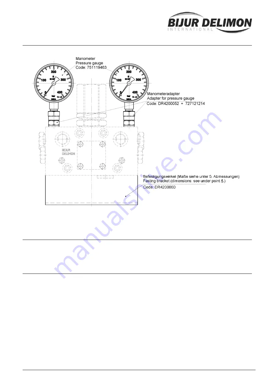
2 x pressure gauges (with adaptor) and mounting brackets (for fixing onto the basic frame)
3. Application
The DR4 is an hydraulically operated directional control valve for use with dualine or non-return systems.
4.
Principle of operation
The reversing valve’s switching pressure depends on the spring pressure, which can be set for
installation. After the activation of all dual-line metering valves in the lubricating system, pressure is built
up against a guide piston, which in turn acts on a rocker arm. If the force acting on the rocker arm is
equal to the spring force, it moves into the other end position. This directs a control current towards one
end of the piston, which determines the direction of flow. The piston moves, thereby freeing at the other
end the passage to the tank. Accordingly the pump’s delivery flow is directed into the opposite line and
the pressure is taken off the originally pressurised line back to the tank.
An electric switch, which is activated by means of a pin attached to the control piston in the direction of
flow, is mounted on the reversing valve. When the switch is activated by the pin, either to open or close it,
a signal is sent to the control to either stop the pump or start a switching interval.
The diagram and the details on pages 4 clarify the mode of operation. The following mode of operation is
available for use in dual-line lubrication systems.
On the DR4 valve (non-return system), the two pipelines do not return to the reversing valve but the
reversal pressure is sufficient for the operation of all the measuring valves.


