


Installation, Operation and Maintenance Manual
September 2019
MAN720_IMVS2000v2_IOM Rev. 6
Section 9: Wiring Diagrams - SIgnals Description
Wiring Diagrams - Signals Descriptions
9.1.2.2
Modbus Card Signals
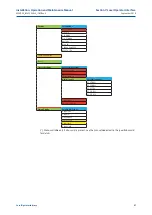
Figure 17
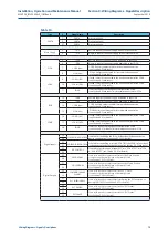
The previous figure shows the terminals of the IMVS2000v2 MODBUS Card.
The table below describes the signals of the of the MODBUS Card terminals (for details see [3]).
Table 12.
Type
#
Signal Name
Description
MODBUS
42, 45
MODBUS-B
Modbus data line B (+).
43, 46
MODBUS-A
Modbus data line A (-).
44, 47
MODBUS-R
Modbus Reference line.
SHIELD
48
SHIELD
Available connection for the cable Shield.
It is connected to the Protection Earth through a 2.2nF 4KV capacitor.
EARTH
49
EARTH
Protection Earth.
77
Содержание IMVS2000v2
Страница 2: ......