ENGLISH
DESCRIPTION
SUSETTE water cleaners are suitable for the professional use whe-
re a high temperature and high pressure washing isneeded.
Water is pushed forward by a high pressure pump, A.P pump, th-
rough the hydraulic circuit up to the heating coil heated by a gasoil bur-
ner. It can be equipped with an external detergent tank whose quantity
can be regulated, mixed whith water and delivered with low pressure.
The operator points the water jet at the surface to be cleaned or degrea-
sed operating the lance and pulling the automatic handle lever. If the
automatic hand lelever is realesed, water jet will stop immediately.
In the by-pass models, the pump will recycle water. In the total
stop models, the burner will stop and the pump recycles water for so-
me second before stop.
Attention
The water cleaner main technical features are detailed
on an adhesive nameplate placed on the watercleaner
base plate.
GENERAL ADVICE
• Follow the instructions in this manual carefully
• Do not place inflammable materials near the machine (min. di-
stance 3mt.)
• Use the water cleaner out doors or in a well ventilated place. An
electrics witch board with suitable characteristics should be near
the machine.
• Do not use electrical extensions
• Do not point the water jet at the water cleaner or other electrical
parts
• Do not use dirty or sandy water nor inflammable, chemical or
corrosive products
• Do not point the water jet at people, animals or electrical parts
• Check the machine before use and don't let animals or children
near the machine
• After use make sure the disconnecting switch is off.
INSTALLATION
PACKAGING REMOVAL
To remove packaging used for shipment:
• remove the plastic strap used to fix the machine to the wooden
base
• lift the carton box up
• remove the boards fixed on the wooden base which lock the
wheels and
• push slowly the water cleaner down the base
Attention
Never try to lift the machine manually. Doing so could re-
sult in physical injury.
ELECTRICAL CONNECTIONS
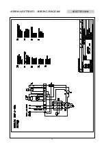
The water cleaner Susette 120 M is equipped to be connected to
single phase power mains, 50 Hz, 230 V.
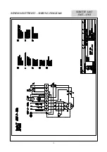
The other models, that is to say Susette 120T, 150 T, 170 T, are
equipped to fit three-phase power mains, 50 Hz, 400. Models 120T and
150T can be also equipped to fit three-phase power mains, 50 Hz, 230
V (see "Power supply voltage variation").
Attention
The power mains must be earthed and have a magneto-
thermal switch with differential.
The machines with three-phase electrical feeding, have power sup-
ply characteristics detailed on the adhesive label stcked on the motor-
hood: before connecting the power lead, check that they correspond to
those of the fixed electrical plant.
POWER VOLTAGE VARIATION (THREE-PHASE MODELS ONLY)
The water cleaners are standard fitted to be connected to three-
phase power mains, 50 Hz, 400 V. If the electric equipment should be
changed to 230 V or vice-versa to fit other kind of power mains, the fol-
lowing operations must be carried out:
• replace the magneto-thermal switch, setting the thermal relay to
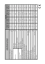
the value indicated in the technical features scheme.
• connect the small bars of the motor terminal board as indicated
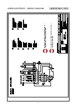
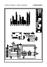
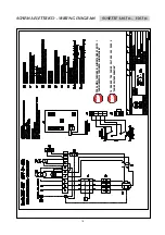
in the electrical schemes included in this manual.
• move the jumper on control unit (AP) to 0 - 230V.
• replace the adhesive label with another one showing the selected
voltage.
LANCE PREPARATION
The pakaging contains:
• high pressure hose, AP, already connected to the automatic
handle and to the fixed semi-lance.
• the mobile semi-lance, already prepared with the water nozzle to
beused and only for AR models, the adjustable nozzle head.
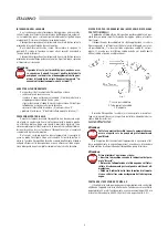
After screwing the fixed semi-lance on the mobile one, connect the
AP hose to the water exit connection on the water cleaner,
screwing the rapid connection fitting.
WATER MAINS CONNECTION
Connect a rubber hose with 19 mm. internal section to the water
entrance pipe of the water cleaner by means of the hose coupling al-
ready screwed.
The hose from the water supply shall be fre of incrustation and im-
purities, which may compromise the proper functioning of the cleaner.
For the water cleaner to operate regularly, the feeding pressure
should beat least 1,5-2 bar: lower pressures may cause the AP pump to
suck airin.
GASOIL TANK
The fuel tank must be filled with clean gasoil only, avoiding acci-
dental introduction of water or any other impurity.
INSTRUCTIONS FOR USE
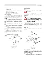
SWITCHING ON AND WASHING
• open the water mains cock.
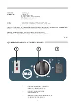
• switch the water cleaner on pressing the magneto-thermal switch
black key" I " (1).
• pull the automatic handle lever and point the water jet at the sur-
face tobe cleaned.
• If you intend to use hot water:
• press the burner switch (2) to ;
• turn the thermostat knob (3) to reach the desired temperature.
• if you intend to use detergent: rotate clock wise the adjustable-
nozzle head; the detergent quantity can be preset opening or clo-
sing the detergent dispenser placed on the hydraulic circuit after
the security valve. When finished, rotate anticlock wise the adju-
stable nozzle head.
WASHING STOPPAGE
If you want to stop washing for a while, just release the automatic
handle lever.
In the by-pass models the water jet will immediately stop, and the
AP pump recycles water. The water cleaner will automatically restart by
pulling the automatic handle lever: the water jet restarts.
In the total stop models the water jet will immediately stop, the
burner cuts out and the A.P. pump recycles water for some seconds
before stop. The water cleaner will automatically restart by pulling the
automatic handle lever: the water jet and the burner restart.
Attention
Stoppage time for by-pass models must not be longer
than 5 minutes in bypassmodels.After this time the pump
head may heat up and damage the valve seals(cfr."obser-
ved faults, causes and remedies")
8
Содержание SUSETTE
Страница 13: ...SCHEMA ELETTRICO WIRING DIAGRAM SUSETTE 120M 13 ...
Страница 14: ...SCHEMA ELETTRICO WIRING DIAGRAM 14 SUSETTE 120T 150T 170T ...
Страница 16: ...16 SCHEMA ELETTRICO WIRING DIAGRAM SUSETTE 120M ts ...
Страница 17: ...17 SCHEMA ELETTRICO WIRING DIAGRAM SUSETTE 120T ts 150T ts 170T ts ...


