background image

BP-LFP-2725(D)

Revision 1-2

16

G1  Switch position OFF

Please note: The following description applies to the BP-LFP-2725 (pack version), but 

not

 to the BP-LFP-2725D 

(DIN rail version, see G2 "Switch position UPSI").

This is the switch position for long-term storage of the battery. The power consumption of the BMS is  
reduced to an absolute minimum. The main switch of the BMS (Power-MOSFETs) is permanently blocked, which 
means that the main power plug is de-energized. The battery cannot be charged or discharged in this switch 
position. IC

2

 communication with the battery is not possible.

Note that the battery should not be stored for a long time in a completely discharged state, as the BMS never-
theless has a very low power consumption and the batteries also show a certain self-discharge.

When the switch is in the OFF position, the storage life is approx. 1 year at 30 % SOC.

G2  Switch position UPSI

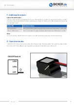
This is the switch position for operation with the UPS 

UPSI-2412

 or 

UPSI-2412D

 from Bicker Elektronik GmbH.

BP-LFP-2725D

: BP-LFP-2725D: In the DIN rail version of the battery the switch is delivered in the 

UPSI

 switch 

position. It 

cannot

 be operated without opening the housing.

Both the communication plug and the main power cable must be connected to the UPS system. The UPSI-
2412(D) controls the connection and disconnection of the battery via the system present function of the 8-pin 
communication connector. All necessary information is transferred to the UPSI-2412(D) via the SM bus: current 
flow, individual cell voltages and state of charge. The protocol is based on the "Smart Battery Data Specification 
v1.1". 
Please note: After a complete backup operation of the UPSI-2412(D) together with the battery, it should be 
recharged as soon as possible. If the input voltage returns to the UPS, it will automatically start charging the 
battery.

If the UPS with connected discharged battery is not put in operation again for more than two weeks, the battery 
may be deeply discharged.

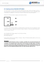
IMPORTANT:
The switch position 

UPSI

 is available twice on the switch. The switch settings are the same in normal de-

livery. On request, the 

ON

 position can be activated by a jumper. The ON position allows the user to use 

the battery without a Bicker UPS in the top switch position. In this position, various energy-saving modes 
are forcibly inactive because the pack has to be always on standby. As this significantly increases the risk 
of deep discharge in the event of accidental activation, this function is standardly deactivated. 

Содержание BP-LFP-2725

Страница 1: ...User Manual BP LFP 2725 BP LFP 2725D Bicker Elektronik GmbH Ludwig Auer Stra e 23 86609 Donauw rth Germany English...

Страница 2: ...in the domestic waste Ne pas jeter avec les ordures m nag res Warning of electrical voltage Avertissement de tension lectrique Battery intended for recycling Batterie destin e au recyclage Date Chang...

Страница 3: ...BP LFP 2725 D Revision 1 2 3...

Страница 4: ...E5 Deep discharge 14 E6 SMBus 14 E7 Discharging process 14 E8 Charging process 14 F Additional functions 15 G Operation modes 15 G1 Switch position OFF 16 G2 Switch position UPSI 16 G3 Switch position...

Страница 5: ...sts When working with the battery care must be taken that no jewelry such as rings or watches are worn which can cause a short circuit A Features BP LFP 2725 D 25 6VDC 2 5Ah 10 year long life battery...

Страница 6: ...light is to be avoided The battery should be kept out of the reach of children The battery must not be short circuited or connected with the wrong polarity The connection cables and plugs of the batte...

Страница 7: ...e naked eye or face Immediately transfer the affected person to an emergency care center Measures in case of skin contact Contact with the contents of an opened cell can cause burns If skin contact oc...

Страница 8: ...8 3x Black Minus AWG 18 Cable length 415mm 10mm Pack version 315mm 10mm DIN Rail version Plug WST WELISHENG TERMINAL P N P6 I42002 AWG 22 Cable length 415mm 10mm Pack version 315mm 10mm DIN Rail versi...

Страница 9: ...cuit switch off 64A 200 s Fuse 20A Own power consumption in energy saving mode 100 A max Maximum installation height 5000 m CHARGING PARAMETERS Recommended end of charge voltage 27 6 V 0 02 V Charging...

Страница 10: ...nge 25 C 5 C Maximum temperature range 25 C 55 C Recommended SoC 80 APPROVALS UN38 3 IEC EN IEC EN62133 3 Backup time depends on battery capacitance load and temperature At very high or low temperatur...

Страница 11: ...S Unless otherwise stated Tolerance according to DIN ISO 2768 T1 m DIN ISO 2768 T2 K BP LFP 2725 415 00 108 00 70 00 63 00 BP LFP 2725D 120 00 100 00 9 00 65 00 100 00 Unless otherwise stated Toleranc...

Страница 12: ...permanent fault occurs during operation e g loss of a cell voltage tap deep discharge the battery remains permanently deactivated and can only be re enabled by the manufacturer after troubleshooting L...

Страница 13: ...ratures the charging and discharging be haviour in conjunction with your application should be checked The cell characteristic leads to a different voltage behaviour of the cells E3 Balancing The BMS...

Страница 14: ...to end of discharge voltage 0 SoC Depending on current the remaining capacity decreases continuously If the battery management system detects an error it will be shut down as described in Section Func...

Страница 15: ...SFET main switch is not enabled despite activated Syste Present function G Operation modes The BP LFP 2725 has a switch on the cable side of the pack near the cable outlets This switch has three modes...

Страница 16: ...opening the housing Both the communication plug and the main power cable must be connected to the UPS system The UPSI 2412 D controls the connection and disconnection of the battery via the system pr...

Страница 17: ...ged and charged accor ding to the given limit values Recommended end of charge voltage 27 6V 3 45V per cell level Max discharge current 15A Max charge current 6A The maximum capacitive load the batter...

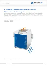
Страница 18: ...adjacent components For this DIN rail versions vertical mounting on a horizontal rail DIN rails according to EN 60715 is recommended in order to achieve the best possible convec tion of the UPS Anoth...

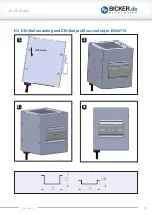
Страница 19: ...BP LFP 2725 D Revision 1 2 19 H2 DIN Rail mounting and DIN Rail profile according to EN 60715 2 3 4 1 Push down...

Страница 20: ...oses of recycling or disposal are excluded from air freight unless authorized by the competent national authorities of the country of origin and the country of the executing company IATA DGR SP A183 T...

Страница 21: ...DR RID SP 188 IMDG SP 188 IATA PI 965 966 967 each section II For detailed transport instructions please refer to the safety data sheet K Disposal instructions Used battery modules must be returned at...

Страница 22: ...6609 Donauw rth Germany Tel 49 0 906 70595 0 Fax 49 0 906 70595 55 E Mail info bicker de www bicker de Note Subject to errors and technical modifications Windows is a registered trademark of the Micro...

Отзывы: