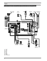


Electronic control p.c.b.
22
9.6
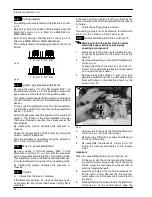
Setting jumpers
Two setting jumpers are fitted on the Electronic control
p.c.b.
Refer to Fig. 35 for the position of the jumpers when the
Electronic control p.c.b. is fitted on a M90D.24S or
M90D.28S boiler.
Refer to Fig. 36 when the Electronic control p.c.b. is
fitted on a M90D.24SR or M90D.28SR boiler.
The numbers refer to the marking printed on the circuit
board.
1 2 3 4 5 6 7 8 9
Fig. 35
1 2 3 4 5 6 7 8 9
Fig. 36
9.7
Ignition gas pressure adjustment
By using the device ”10” (Fig. 28) marked “ACC.” on
the Electronic control p.c.b., it is possible to adjust the
gas pressure at the injectors in the ignition phase.
This pressure is maintained at the injectors until ignition
occurs (ionization signal from the full sequence ignition
device).
To carry out the adjustment move the function selector
3 to the OFF position (Fig. 33) and use the adjustment
device ”10” (ACC).
Adjust the gas pressure at the injectors to the value indi-
cated in the tables of the User/Installation manual
(
Technical information
section,
Gas pressures at the
burner
table).
By rotating the device clockwise the pressure in-
creases.
Check the regular ignition of the burner by turning the
boiler on and off repeatedly.
After the adjustment operations bring the selector 3
back to the normal position (ON).
9.8
Max c.h. power adjustment
By using device 11 (Fig. 28) marked “RISC.” on the
Electronic control p.c.b., you can limit the maximum
useful output delivered during the c.h. operating mode.
This adjustment does not influence the maximum use-
ful output delivered during the d.h.w. operating mode.
By rotating the device clockwise the pressure in-
creases.
9.9
Checks
n
Check that the fuse is complete
If the Electronic control p.c.b. does not supply any de-
vice (pump, fan, etc.) check that the fuse 13 (Fig. 28) is
complete.
If the fuse has blown replace it with one that has the
same characteristics after having identified the reason
for failure.
n
Check the setting jumpers position
Two setting jumpers must be fitted on the Electronic
control p.c.b. as shown in Fig. 35 and Fig. 36.
9.10
Removal of the electronic control p.c.b
Warning: isolate the boiler from the mains
electricity supply before removing any
covering or component.
1
Gain access to the parts located inside the con-
trol panel as explained in the section 2.3 of this
manual.
2
Remove all the wiring connected to the Electronic
control p.c.b..
To disconnect the connectors J1, J2 and J3 (12,
2 and 1 in Fig. 28) delicately flex the hook present
on one side of each socket.
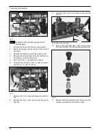
3
Remove the spindles of the c.h. and d.h.w. tem-
perature adjustment knobs by delicately pulling
them with pliers in the direction shown by the
arrow in Fig. 37.
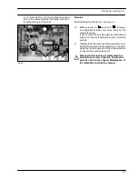
Fig. 37
4
Unscrew the four screws that hold the Electronic
control p.c.b. on to the control panel.
5
Remove it by lifting its rear edge and freeing it
from any of the wiring.
6
Re---assemble the Electronic control p.c.b. fol-
lowing the removal procedures in the reverse
order.
Important
When re---assembling the Electronic control p.c.b.:
7
Fit the p.c.b. into the control panel by first insert-
ing the front lower edge under the control knob
shafts. Lower the rear edge and ensure that no
wiring is trapped beneath.
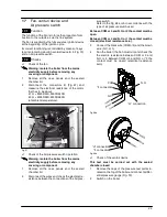
8
Insert the spindles in the control panel knobs un-
till the notch
A
(Fig. 38) reaches the potentio-
meter edge. It is not necessary to force them in
the knob.
9
While tightening the screws that fix the Electronic
control p.c.b. on the control panel, keep the
Содержание RIVA PLUS M90S.24S
Страница 2: ......
Страница 43: ...Short spare parts list 41 1 2 6 4 5 7 3 8 15 18 12 13 20 21 22 23 25 26 14 16 24 17 19 9 10 11 9...
Страница 44: ...1796209146 17962 0914 6 3804 44A4 UK...


