


- 22 -
ElEctronic control/ignition p.c.b.
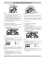
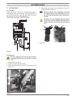
edge and ensure that no wiring is trapped beneath.
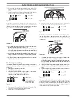
8 Insert the spindles in the control panel knobs until the notch A
(Figure 8.26) reaches the potentiometer edge. It is not neces-
sary to force them in the knob.
9 While tightening the screws that fix the Electronic control/igni
-
tion p.c.b. on the control panel, keep the p.c.b. towards the
control panel fascia making sure of the contact between the
boiler reset button B and the tab C (Figure 8.26).
figure 8 .26
a
a
b
c
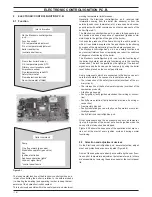
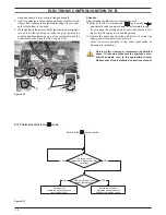
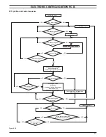
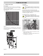
8 .12 thermal control in the mode
Switch in the function mode
Is primary circuit
temperature higher than that
selected?
NO
Request for heat from
room thermostat?
Starts the circulator
Operates motorised valve
Supplies the ignition device
NO
Circulator off
Operates motorised valve
Ignition device off
YES
YES
figure 8 .27
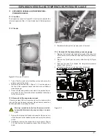
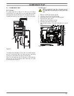
attention
After installing the Electronic control/ignition p.c.b. :
10 Make sure the c.h. temperature (
) and service (
)
adjustment knobs can move freely for the complete range.
If not, remove the spindle again as described at step 3, turn
the knob half a turn and re-insert the spindle.
11 Operate the boiler and close the gas inlet cock so that the
boiler goes into the safety lock-out state.
Verify the correct operation of the boiler reset button by
pressing and releasing it.
warning: after cleaning or replacement as detailed
above, if it deemed necessary to undertake a com-
bustion analysis, refer to the appropriate chapter
maintenance of the installation instructions manual .
Содержание Riva Plus HE M296.24SR/C
Страница 2: ......
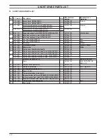
Страница 37: ...37 Short spare parts list 1 2 6 4 5 7 3 8 13 12 2 2 1 2 19 7 1 5 1 14 20 9 10 11 9 16 23 18 Figure 19 1...
Страница 38: ...38 NOTE...
Страница 39: ......