


- 18 -
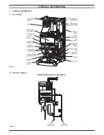
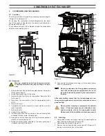
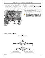
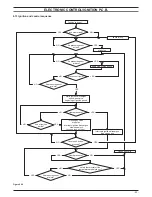
ElEctronic control/ignition p.c.b.
Normally operating boiler
(see the previous table for details)
C.h. operation
Frost protect operation
Faulty c.h. temperature probe NTC
Faulty flue temperature probe NTC
Faulty primary circuit
(no water or low c.h. pressure)
Faulty primary circuit
(absence of flow)
Faulty air pressure sensor
Lack of burner ignition (no ignition signal from
the full sequence ignition device)
Safety thermostat lock out
Flue temperature probe NTC lock out
Flame detection error
Flame detection error
Lack of power supply or fauly electronic
control p.c.b. *
Lamp OFF
Lamp ON
Flashing lamp,alone or simultaneously
with another lamp
Flashing lamp, alternate with another lamp
* These conditions are normal only for a short time when the
power supply is applied to the boiler.
If permanent they indicate a faulty p.c.b.
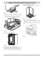
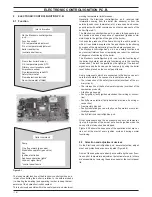
8 .5 setting the boiler control function modes
It is possible to select the various boiler control function modes
by using the function selector knob A and the d.h.w. temperature
control knob B (Figure 8.4).
During the function modes setting, the boiler does not operate.
figure 8 .4
a
f
b
d e
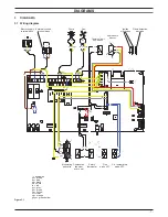
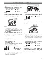
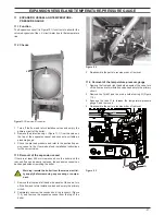
8 .6 useful output setting
To set the useful output proceed as follows:
1 Remove the front panel of the case.
2 Take off the lid of the sealed chamber.
3 Switch on the appliance at the mains isolating spur.
4 Turn the boiler OFF positioning the function selector A as in-
dicated in Figure 8.5.
figure 8 .5
f
b
a
d
e
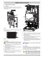
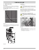
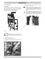
5 Disconnect the electrical connectors C of the c.h. tempera-
ture probe NTC in Figure 8.6.
figure 8 .6
c
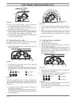
6 Keep pressed the reset button D for about 10 seconds until
the lock-out signal lamp E blinks.
7 Connect the electrical connectors C of the c.h. temperature
probe NTC in Figure 8.6.
8 The lamps F should give the indication as in Figure 8.7 (use-
ful output, first step). If not, press the reset button repeatedly
to obtain it.
figure 8 .7
Where:
Lamp OFF
Lamp ON
At this step it is possible to visualize the current setting by keep-
ing the reset button D pressed for more than 5 seconds. The
lamps F
will flash a number of times corresponding to the setting
Figure 8.8 (once for M296.24SR/C, four times for M296.28SR/C).
figure 8 .8
M296.24SR/C
1 flash
M296.28SR/C
4 flashes
b
9 To change the setting turn the knob B on a position corre-
sponding to the boiler models (Figure 8.8). By turning the
knob B, the lock-out signal lamp E blinks quickly (2 per sec-
onds) indicating that the setting has changed and must be
memorised.
Содержание Riva Plus HE M296.24SR/C
Страница 2: ......
Страница 37: ...37 Short spare parts list 1 2 6 4 5 7 3 8 13 12 2 2 1 2 19 7 1 5 1 14 20 9 10 11 9 16 23 18 Figure 19 1...
Страница 38: ...38 NOTE...
Страница 39: ......