Biasi RIVA ADVANCE HE M110.24SM Скачать руководство пользователя страница 37

Commissioning

33

7.8

Maximum output in c.h. mode

The maximum useful output in c.h. mode of model

can be varied and on model M110.32SM/... is fac-

tory set to 24 kW.
To change the maximum useful output value in

c.h. mode refer to the

electronic control/ignition

pcb

section of the service manual

7.9

External temperature probe

setting (optional)

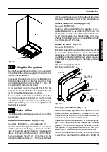
The external temperature probe (if fitted) allows to

adjust automatically the temperature of the c.h.

flow with reference to the external temperature.
The curves given in the chart of Fig. 7.7 represent

the c.h. flow temperature setting as a function of

the external temperature measured by the exter-

nal temp. probe.
The relationship between the external tempera-

ture and the c.h. flow temperature is represented

by the coefficient K (Fig. 7.7) that can be set be-

tween 0 and 6 as hereafter explained.
E.g. to obtain a flow temperature setting of 60

û

C

when the external temperature is ---5

û

C, K must

be set to 1,5 (dashed line in Fig. 7.7).

20

30

40

50

60

70

80

External temperature

û

C

C.h. flow temperature

û

C

20

15

10

5

0

--- 5 --- 10 --- 15 --- 20 --- 25

K=4

K=3

K=2

K=1

K=0,5

K=1,5

K=6

Fig. 7.7
The appropriate value of the coefficient K de-

pends on the design temperatures of the c.h. sys-

tem as the minimum external temperature and the

corresponding c.h. flow temperature.

The coefficient K is factory set to 0 that is the

setting for the operation with no external tem-

perature probe fitted.

To set the coefficient K:

1 Turn on the electricity supply to the boiler,

switching on the fused spur isolation switch.

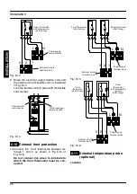
2 Set the function knob 8 as illustrated in Fig. 7.8.

8

10

7 6

9

Fig. 7.8
3 Keep pressed the reset button 7 for about 10

seconds until the lock---out signal lamp 6

blinks.

4 The lamps should give the indication as in

Fig. 7.9 (coefficient K setting). If not, press the

reset button repeatedly to obtain it.

Where:

Lamp OFF
Lamp ON

Fig. 7.9
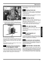
5 To change the setting turn the knob 9 on a posi-

tion corresponding to the desired coefficient K.

By turning the knob 9, the lock---out signal

lamp 6 blinks quickly (2 per seconds) indicat-

ing that the setting has changed and must be

memorised.

Setting No.

Coeff. K

1

4

2

3

5

6

7

0

0,5

1

1,5

2

3

6

4

9

5

Fig. 7.10
6 To memorize the setting keep pressed the

reset button 7 for about 5 seconds until the

lights 10 briefly blinks simultaneously.

7 To reset the boiler to the normal operation turn

it OFF and ON by the function selector knob 8.

INST

ALLA

TI

ON

Содержание RIVA ADVANCE HE M110.24SM

Страница 1: ...Wall hung fan flue room sealed high efficiency gas boiler User manual and Installation instructions RIVA ADVANCE HE Models M110 24SM C M110 32SM C...

Страница 2: ...as tight is of the correct gauge for the flow to the boiler is fitted with all the safety and control de vices required by the current Regulations n Ensure that the installer has connected the pressur...

Страница 3: ...ot present high risk follow good hygiene prac tices wash handsbefore touching eyes consum ing food drinking or using the toilet First aid Medical attention must be sought fol lowing eye contact or pro...

Страница 4: ...hat the water temperature exceeds the design temperature n You are strongly advised to flush out the system both cold and hot in order to remove system and installation debris n It is also sensible to...

Страница 5: ...24 6 6 Mounting the boiler 24 6 7 Fitting the flue system 25 6 8 Choice of flue 25 6 9 Electrical connections 26 6 10 External frost protection 28 6 11 External temperature probe optional 28 7 Commis...

Страница 6: ...reset button 8 Function selector and c h temp control knob 9 D h w temperature control knob 10 Appliance operation lights 1 3 Isolation valves 14 12 16 13 15 11 Fig 1 2 bottom view of the boiler 11 C...

Страница 7: ...e lights combination observed is not included in the above table a fault may be indicated Reference should be made to the following table In this case switch off the boiler as described in section 2 6...

Страница 8: ...staller or an Approved Engineer This appliance is provided with a built in anti freeze system that operates the boiler when the temperature is below 5 C Therefore when the boiler is not lit or used in...

Страница 9: ...nimum of about 25 C to a maximum of about 85 C Fig 2 6 by turning the knob 8 Adjustment of the boiler temperature alters the gas flow at the burner according tothe thermalde mand in the system So it i...

Страница 10: ...e The temperature of the d h w leaving the boiler can be varied from a minimum of about 35 C to a maximum of about 55 C Fig 2 9 by turning the temperature control knob 9 9 Minimum Maximum Fig 2 9 Adju...

Страница 11: ...pliance operation light 10 will flash every 4 seconds 8 10 Fig 2 11 When you donot expectto use the boiler for along period 1 Switch off the electricity supply to the boiler by means of the fused spur...

Страница 12: ...Set the OFF time as explained above for the ON setting and confirm by pressing the enter button C Proceed in the same way for other settings Setting example shown in Fig 2 16 A ON time 7 45 day Monday...

Страница 13: ...ermanently on or off by pressing the button F and leaving the switch A in the TIMER position To force a timed delay on or off operation set the mode selector switch A in the TIMER position Set the tim...

Страница 14: ...ation of the expansion tank filling up of the central heating circuit bleeding of air from thecentral heating system general check of the appliance s operation 3 4 External cleaning Before carrying ou...

Страница 15: ...the central heating circuit is not close to 3 bars In this case tempera ture rise in the circuit can cause the pressure relief valve to open So that this does not happen and to decrease the pressure t...

Страница 16: ...h pressure relief valve 25 Automatic air purger valve 26 Main circuit drain valve 27 Pump 28 Pump vent plug 29 Gas valve 30 D h w temperature probe NTC 31 Primary circuit flow switch 32 Condensate tra...

Страница 17: ...Technical information 13 4 2 Main diagram 48 47 31 19 37 27 24 40 29 41 25 34 33 44 45 12 13 16 14 43 35 21 18 30 15 20 38 26 46 32 11 39 49 50 17 42 Fig 4 2 INSTALLATION...

Страница 18: ...5 Minimum temperature C 35 Maximum pressure kPa bar 1 000 10 Minimum pressure kPa bar 30 0 3 Flow rate minimum l min 2 5 30 rise D l min 12 4 35 rise D l min 10 4 40 rise D l min 9 1 Gas supply pressu...

Страница 19: ...C 85 Smoke production E kg h 42 CO2 contents CO2 content range min max 8 3 9 3 At nominal heat input of 25 0 kW A E CO2 content range min max 8 8 9 0 At minimum heat input of 6 0 kW A E Other flue gas...

Страница 20: ...e C 55 Minimum temperature C 35 Maximum pressure kPa bar 1 000 10 Minimum pressure kPa bar 30 0 3 Flow rate minimum l min 2 5 30 rise D l min 16 5 35 rise D l min 14 0 40 rise D l min 12 1 Gas supply...

Страница 21: ...80 Smoke production E kg h 58 CO2 contents CO2 content range min max 8 3 9 3 At nominal heat input of 33 5 kW A E CO2 content range min max 8 8 9 0 At minimum heat input of 11 0 kW A E Other flue gas...

Страница 22: ...i mum flow through the primary heat exchanger of the boiler in the event that the flow around the cen tral heating circuit is restricted due to closure of thermostatic or system control valves 4 6 Exp...

Страница 23: ...rawn tothe requirementsof the current I E E Wir ing Regulations and in Scotland the electrical provisions of the Building Regulations applicable in Scotland with respect to the installation of the com...

Страница 24: ...e both to the boiler and the other appliance when they are in use at the same time Pipework must be of adequate size Pipes of a smaller size than the boiler inlet connection should not be used Install...

Страница 25: ...a system that includes thermo static radiator valves TRV and or small bore 8 10 mm it may be necessary to fit an external by pass to facilitate correct operation of the boiler The fitting of an extern...

Страница 26: ...e new appliance is maintained Details on flushing procedure are given in the sec tion 7 4 of this manual Domestic hot water circuit scale protection In areas where the water is hard i e more than 200...

Страница 27: ...ce procedures it is necess ary to leave the minimum gaps indicated in Fig 6 1 25 50 200 200 Fig 6 1 all dimensions in mm When installing the boiler in a cupboard cover or alcove allow at least50mm per...

Страница 28: ...25 plastic Tab 6 1 sizes in mm o d 6 6 Mounting the boiler 1 Take the protective caps off the boiler pipe work 2 Thoroughly clean the connections 3 Mount the boiler on its bracket 4 Fix the c h valves...

Страница 29: ...rge horizontally it is not de signed to enable termination in the vertical plane Vertical kit with 90 elbow Fig 6 5B Co axial 60 100 mm Supplied with a straight flanged adapter a co axial elbow and a...

Страница 30: ...ional 45 and 90 elbowscan beused tooffset the flue route Each additional elbow reduces the overall accept able length of the flue system as follows 45 reduce length by 0 5 m 90 reduce length by 1 m ma...

Страница 31: ...re yellow green Connection of a room thermostat The room thermostat must be connected to the terminal block situated next to the control panel Any external controls and connection lines must be rated...

Страница 32: ...6 14 6 10 External frost protection 10 Connect the frost thermostat between ter minals 1 and 2 as shown in Fig 6 15 or Fig 6 16 Do not connect live wires to terminals to which the frost thermostat mu...

Страница 33: ...ec tricwireswhich conform tothe currentregulations with flexible cord each core having a cross sec tion area not less than 0 50 mm2 The connection wiring of the external tempera ture probe is part of...

Страница 34: ...inuity resis tance to earth and short circuit If a fault has occurred on the appliance the fault find ing procedure should be followed as specified in the service manual 7 2 Gas supply installation 1...

Страница 35: ...the use of a c h flushing detergent in the quan tities as specified by the appropriate manufac turer whose function it is to dissolve any foreign matter which may be in the system INHIBITION Primary H...

Страница 36: ...he boiler during oper ation In these circumstances it maybe necess ary to reset the gas valve in accordance with the section 11 Gas Valve of the Service Manual It should be noted that a flue gas analy...

Страница 37: ...7 7 The appropriate value of the coefficient K de pends on the design temperatures of the c h sys tem as the minimum external temperature and the corresponding c h flow temperature The coefficient K...

Страница 38: ...s given in the section 8 5 of this manual Reference figures are given in the sections 4 3 or 4 4 of this manual Flue gas figures 7 12 Checking the condensate drain pipe Check the soundness and integri...

Страница 39: ...n off the gas cock before carrying out any pro cedures whatsoever for cleaning mainten ance opening or dismantling boiler panels 8 2 Dismantling the external panels Front panel 1 Loosen the three scre...

Страница 40: ...ven in the sections 4 3 or 4 4 of this manual 8 6 Cleaning the condensing heat exchanger and burner To remove the burner fan group D Fig 8 5 1 Take off the front and side panels of the case 2 Remove t...

Страница 41: ...reach the burner do the operations described in the section 8 6 of this manual 8 9 Checking the flue Have the integrity of the flue outlet pipe 47 on page 13 air intake pipe 48 on page 13 checked peri...

Страница 42: ......

Страница 43: ......

Страница 44: ...796211180 17962 1118 0 1406 44A5 UK Biasi U K Ltd Unit 31 33 Planetary Road Industrial Estate Neachells Lane Willenhall Wolverhampton WV 13 3XB Technical helpline 01902 304 400 Web site www biasi co u...

Отзывы: