


30
7
Commissioning
WARNING
The commissioning of this boiler and system
must only be undertaken by a professionally
qualified person in accordance with the re-
quirements of the Gas Safety Installation and
Use Regulations and be approved by
C.O.R.G.I.
Ensure that the Benchmark Log Book is satis-
factorily completed during the commissioning
process. The Log Book is located at the end of
this manual. This manual should be handed to
the User following completion of the installa-
tion and commissioning process. Failure to
comply with these requirements may invali-
date the manufacturers guarantee.
For Ireland (IE), it is necessary to complete a
“Declaration of Conformity” to indicate com-
pliance to I.S.813.2002.
7.1
Electrical installation
Preliminary electrical system checks to ensure
electrical safety shall be carried out by a compet-
ent person. i.e. polarity, earth continuity, resis-
tance to earth and short circuit.
If a fault has occurred on the appliance the fault find-
ing procedure should be followed as specified in the
service manual.
7.2
Gas supply installation
1 Inspect the entire installation including the gas
meter, test for soundness and purge, all as de-
scribed in BS 6891;
For Ireland (IE), refer to I.S.813.2002.
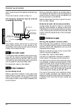
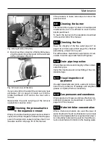
2 Open the gas cock 14 (Fig. 7.1) on the
appliance and check the gas connector on the
appliance for leaks.
Open position
14
13
Fig. 7.1
7.3
Filling the d.h.w. system
1 Close all hot water draw---off taps.
2 Open the cold water inlet valve 13 (Fig. 7.1).
3 Slowly open each draw---off tap and close it
only when clear water, free of bubbles, flows
out.
7.4
Initial filling of the system
1 Open the c.h. flow and return valves.
2 Remove the front and side panels of the case
(see the section 8.2 in this manual) and the
sealed chamber lid.
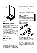
3 Unscrew the condensing heat exchanger air
purger valve 17 (Fig. 7.2).
17
Fig. 7.2
4 Unscrew the cap on the automatic air purger
valve 25 (Fig. 7.3) one full turn and leave open
permanently.
INST
ALLA
TI
ON


