


Technical information
18
4.5
Hydraulic specifications
0.0
0.1
0.2
0.3
0.4
0.5
0.6
0
200
400
600
800
1000 1200 1400
0
10
20
30
40
kPa bar
l/h
60
50
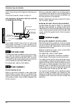
Fig. 4.3 model M110.24SM/...
0.0
0.1
0.2
0.3
0.4
0.5
0.6
0
200
400
600
800
1000 1200 1400
0
10
20
30
40
kPa bar
l/h
60
50
Fig. 4.4 model M110.32SM/...
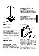
The hydraulic specifications in Fig. 4.3 and
Fig. 4.4 represent the pressure (available head for
the central heating system) as a function of the
flow rate.
The load loss due to the boiler has already been
subtracted.
Operation of integral By---pass valve
The boiler is fitted with an automatic by---pass
valve (44 on page 12), which protects the primary
heat exchanger.
The integral automatic by---pass will ensure a mini-
mum flow through the primary heat exchanger of
the boiler in the event that the flow around the cen-
tral heating circuit is restricted due to closure of
thermostatic or system control valves.
4.6
Expansion vessel
Note: this boiler is designed for operation only
in a sealed central heating system
The height difference between the pressure relief
valve and the highest point in the system may be
7m at most.
For greater differences, increase the pre---load
pressure in the expansion vessel (43 on page 12)
and the system, when cold, by 0.1 bar for each
additional 1m.
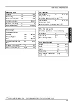
Capacity
l
7,0
Pre---load pressure
kPa
bar
100
1,0
Maximum volume of water
in the system *
l
154
Tab. 4.1
* Where conditions are:
---
Average maximum temperature of the system
is 80
°
C
---
Initial temperature when filling up the system is
10
°
C
For systems with volumes greater than 154l, an
additional expansion vessel must be provided.
INST
ALLA
TI
ON


