


Instruction for use
6
Always ensure that the pressure gauge is set
at the required pressure.
Следует
периодически
проверять
показания
манометра
.
2.3. Ignition
2.3
Розжиг
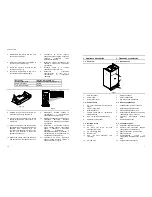
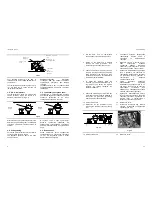
1 Check that gas inlet cock located in the
lower part of the boiler is open (Fig. 2.3).
1
Проверьте
,
чтобы
краны
,
расположенные
в
нижней
части
котла
были
открыты
(
Рис
. 2.3.).
Open position
gjkj;tybt jnrhsnj
Fig. 2.3
2 Turn on the electricity supply to the boiler,
switching on the fused spur isolation
switch. The appliance operation light 9
(Fig. 1.3) will flash every 4 seconds
(stand-by condition).
2
Включите
электропитание
котла
.
Индикатор
котла
9 (
рис
.1.3.)
будет
моргать
каждые
4
секунды
(
состояние
ожидания
).
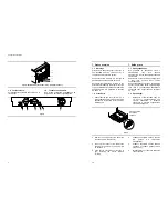
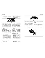
3 If the boiler is to be used for C.h. and
D.h.w position the function selector 7 as
in Fig. 2.4. The appliance operation light 9
will flash every 2 seconds (operating
boiler).
3
Если
котел
должен
работать
в
режиме
отопления
и
приготовления
горячей
воды
,
переключатель
7
должен
находиться
в
положении
,
как
указано
на
рис
. 2.4.
Индикатор
котла
9
будет
мигать
каждые
2
секунды
(
котел
работает
).
9
7
Fig. 2.4
9
7
Fig. 2.5
4 If D.h.w. supply only is required, position
the function switch 7 as in Fig. 2.5. The
appliance operation light 9 will flash every
2 seconds (operating boiler).
4
Если
существует
потребность
только
в
горячей
воде
,
переместите
переключатель
7
в
положение
,
указанное
на
рис
. 2.5.
Индикатор
котла
9
будет
моргать
каждые
2
сек
.
(
котел
работает
).
Commissioning
35
6.6. Adjusting the burner ignition
6.6
Регулировка
розжига
горелки
1 Turn off the boiler by means of the fused
spur isolation switch provided with the
appliance.
1
Отключите
котел
путем
выключения
автомата
,
поставляемого
с
устройством
.
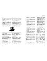
2 Make sure that the function switch 7 is set
to the position in Fig. 6.6 and that the
timer selector switch and room
thermostat, if fitted, is set to “heat
demand".
2
Убедитесь
в
том
,
что
преключатель
7
находится
в
положении
,
как
указано
на
рис
. 6.6,
а
программатор
и
комнатный
термостат
настроены
на
"
запрос
на
отопление
".
9
7
Fig. 6.6
3 Unscrew the gas valve's outlet pressure
test point 35 (Fig. 6.5) and connect a
pressure gauge.
3
Отверните
винт
контрольной
точки
35
газового
клапана
(
рис
. 6.5)
и
подсоедините
прибор
измерения
давления
.
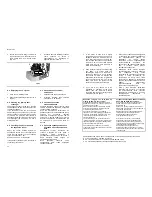
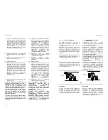
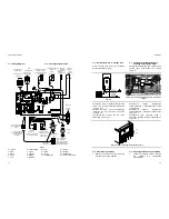
4 Loosen the screws D and remove the
service panel (Fig. 6.7).
4
Ослабьте
болты
D
и
снимите
сервисную
панель
(
рис
. 6.7)
D
Fig. 6.7
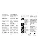
2
3
4
OFF
ON
1
ACC
RISC
+
+
Fig. 6.8
5 Turn on the boiler
5
Включите
котел
6 Check that the boiler lights up uniformly
and adjust the flame height , if necessary.
6
Проверьте
,
чтобы
котел
горел
равномерно
и
при
необходимости
увеличьте
высоту
пламени
.
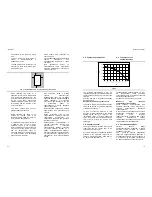
To adjust the ignition gas pressure, set dip-
switch "3" (Fig. 6.8) to the “OFF” position and
adjust potentiometer marked “ACC" with a
screwdriver until correct ignition gas pressure
is obtained.
Чтобы
настроить
давление
газа
на
розжиге
,
переместите
переключатель
"3"
(
рис
. 6.8)
в
положение
"OFF"
и
при
помощи
отвертки
регулируйте
потенциометр
,
обозначенный
"ACC"
до
тех
пор
,
пока
не
получите
необходимое
давление
газа
.