background image

- 21 -

MAIN ElEctroNIc coNtrol/IgNItIoN p.c.b.

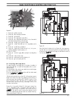
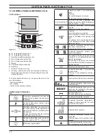
figure 9 .2

1 2

3

4

5

6

7

8

9

10

11

12

13

14 

Connector - ignition electrode.

Connector - flame detection electrode

Connector - controler fan

Connector - flue temperature probe NTC

Connector - d.h.w. temperature probe NTC, d.h.w. flow switch 

and external temperature probe (optional)

Connector - Primary circuit pressure switch

Connector - safety thermostat and c.h. temperature probe 

NTC

Connector - remote control (optional)

Connector - display and function control / c.h. / d.h.w. tem

-

perature adjustment control panel p.c.b.

10 

Fuse F1, F2 2A F

11 

Connector  -  electric  supply  Main  electronic  control/ignition 

p.c.b.

12 

Connector - 3 way diverter valve

13 

Connector - electric supply control panel p.c.b.

14 

Connector - gas valve, pump and fan

9 .3  checking the temperature

The 

Main electronic control/ignition p.c.b.

 makes it possible to 

separately adjust the c.h. water flow temperature and d.h.w. out

-

let temperature.
The temperature of the water is converted into an electric signal 
by means of temperature probes.
The user, setting the desired temperature with the control panel 
p.c.b. key 

 or 

.

If the power requested is lower than 40% of the maximum power 
output then control is achieved by switching ON the burner at 

minimum power, then switching OFF (ON/OFF function). If the 

power requested is higher, then the burner is switched ON at 
maximum power and will control by modulating to 40% of the 
maximum power output.

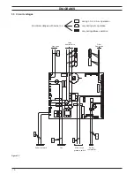
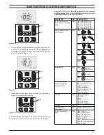
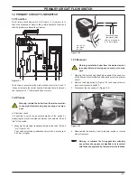
During the c.h. operation (Figure 9.3), the signal coming from 
the c.h. temperature probe is compared to the signal given by 
the control panel through the adjustment made by the user (key 

). The result of such a comparison operates the fan 

speed thus regulating the gas flow rate and consequently chang

-

ing the useful output of the boiler.

figure 9 .3

When the boiler functions in d.h.w. (Figure 9.4), the signal com-
ing from the d.h.w. temperature probe is compared with the sig-
nal given by the control panel through the adjustment made by 
the user (key 

).

figure 9 .4

90 °C

Содержание Inovia 25C ERP

Страница 1: ...0 Inovia 25S ERP 41 583 30 Leave this manual adjacent to the gas meter Warning Service repairs must be carried out only by a qualified Gas Safety Registered Engineer who will be responsible for the cu...

Страница 2: ......

Страница 3: ...the control panel electronic p c b 30 10 6 Removal of the interface electronic p c b 30 11 Gas valve 32 11 1 Function 32 11 2 Description of the parts Figure 11 2 32 11 3 Adjustment 32 11 4 Checks 34...

Страница 4: ...electrodes Expansion vessel Condensate trap C h pressure relief valve D h w heat exchanger Automatic air purger valve Control panel Electric actuator diverter valve D h w temperature probe Airbox air...

Страница 5: ...ws A Figure 2 2 lift the panel and remove it Figure 2 2 A B B Bottom view of the boiler Pull the lower part of the front panel and lift it upwards Figure 2 3 Figure 2 3 C C To remove the side panels l...

Страница 6: ...box Warning isolate the boiler from the mains electrici ty supply before removing any covering or compo nent To gain access to the parts located into main electronic p c b box proceed as follows 1 Rem...

Страница 7: ...the boiler 3 Open the drain tap I Figure 2 11 combi or Figure 2 12 only c h until the boiler is completely emptied 4 To help the draining of the primary circuit loose the condens ing heat exchanger a...

Страница 8: ...bn gnye wh wh gy wh wh wh bu bn bu bn br bu og og gnye bu bn bu bn gnye ye bk ye wh wh bk bk rd rd bk bk bk wh wh wh wh wh t wh bk bk bk bk rd bu bu bu bu bk bk wh wh rd rd rd wh wh rd rd bu bu rd rd...

Страница 9: ...ye bu bn bu bu bn gy bk bu rd rd bu bk bu bn gnye wh wh gy wh wh wh bu bn bu bn br bu og og gnye bu bn bu bn gnye ye bk ye wh wh bk bk rd rd bk bk bk wh wh bk bk bk bk rd bu bu bu bu bk bk wh wh rd rd...

Страница 10: ...ltages with burner on during c h or d h w operation only during c h operation only during d h w operation 230 Safety thermostat 1 Fan 0 Main circuit Supply network 230 0 230 0 3 way diverter valve 230...

Страница 11: ...ger Pump Diverter valve D h w flow switch Fuses Electronic p c b Main electronic p c b Boiler settings Control panel electr p c b Gas valve Main circuit pressure switch D h w filter Main circuit temp...

Страница 12: ...h w temperature 9 Er ind Poor d h w temperature Regular operation in c h mode 8 No Low d h w flow rate Water leaks from the safety valve during operation on c h Water leaks from the safety valve when...

Страница 13: ...d h w temp probe NTC E08 Faulty external temp probe NTC with K set E09 Faulty flue temp probe NTC if present E10 RESET Flue probe intervention lockout if present Flame detection error An flasching er...

Страница 14: ...pipe following the instructions from 1 to 6 in section Removal of the Air box and the Fan page 42 3 Disconnect the detection electrode connector the ignition electrodes connector E and the earth wire...

Страница 15: ...eaning If there are deposits of dirt on the coil of the Condensing heat exchanger clean with a bristle paintbrush and remove the dust with a hoover Warning After cleaning or replacement as detailed ab...

Страница 16: ...the instructions from 4 in section 2 3 4 Remove main electronic p c b box following the instructions from 5 in section 2 4 5 Remove the pump following the instructions in section 7 2 6 Completely uns...

Страница 17: ...iler off remove the front and right hand side case pan els lower the control panel and empty the primary circuit Remove the pump head by undoing the screws which hold it to the pump body and check tha...

Страница 18: ...on of the actuator B brass spindle when the boiler operates in c h mode In both figures the relationship between the position of the actua tor and the resistance of the motor windings the motor must b...

Страница 19: ...that the three way diverter is correctly oriented by matching the reference H with the notch of the water group Figure 8 5 8 5 Removal of the diverter group 1 Remove the front and both side case pane...

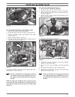
Страница 20: ...nd supplies the fan regulating its speed The Main electronic control ignition p c b has a safety function and any incorrect interventions or tampering can result in condi tions of dangerous functionin...

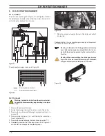
Страница 21: ...temperature and d h w out let temperature The temperature of the water is converted into an electric signal by means of temperature probes The user setting the desired temperature with the control pa...

Страница 22: ...function modes hereafter named parameters by using the keys of the control panel p c b Figure 9 5 A B C 1 To enter in the parameters setting mode press contemporary the 3 keys A B C Figure 9 5 for 10...

Страница 23: ...see chapter COMMISSIONING section Setting record PARAMETER LCD VALUES SET Boiler type to be up dated with the complete range P 01 00 No power Er 99 35 Inovia 25C ERP 36 Inovia 30C ERP 37 Inovia 35C ER...

Страница 24: ...n power P 14 LPG Propane G31 26 Inovia 25C ERP 37 Inovia 30C ERP 31 Inovia 35C ERP 43 Inovia 25S ERP K value external probe diagram P 15 00 Off factory set 01 0 1 60 6 0 K value Min useful output c h...

Страница 25: ...ed adjusted accord ingly with the values noted in table in the installation manual see chapter COMMISSIONING section Setting record for information on parameters see also section 9 4 1 Remove all the...

Страница 26: ...cels lock Is fan rpm exact YES Is flue temperature higher than 110 C YES NO beginning of wait period End of wait period YES NO YES starts ignition discharges Opens gas valve beginning of ignition peri...

Страница 27: ...NO YES NO NO starts fan checks fan rpm YES cancels lock Is fan rpm exact NO YES Is flue temperature higher than 110 C YES NO beginning of wait period flame presence End of wait period YES NO YES star...

Страница 28: ...displayed high lighting the number with the following se quence 1 Mon 7 Sun Constantly illuminated d h w function enabled Flashing d h w function enabled Flashing solar circuit pump in operation Sola...

Страница 29: ...uit temp limit during D h w op eration Boiler Stand By hyphens are turned on in sequence to simulate running antifreeze protection activated LCD FUNCTION In the case of incorrect pressure the value is...

Страница 30: ...o maintenance J15 value 3 star status ON 01 OFF 00 J16 value HWCH Hardware code high J17 value HWCL Hardware code low J18 value SWCH Software code high J19 value SWCL Software code low J20 value 10 4F...

Страница 31: ...nel electronic p c b Figure 10 4 N O P Q R S 4 Unscrew the screws R and Q 5 Remove the Interface electronic p c b 6 Reassemble the Interface electronic p c b carrying out the removal operations in the...

Страница 32: ...oiler switching on the fused spur isolation switch 6 Set the boiler in c h d h w function as illustrated in Figure 11 3 Figure 11 3 C h d h w function 7 Open at least one hot water tap fully 8 Read th...

Страница 33: ...5 Propane G31 9 2 10 2 To adjust the CO2 value remove the brass plug by unscrewing it and rotate the Allen key screw 4 mm C Figure 11 2 by rotating it clockwise the CO2 increases Checking the maximum...

Страница 34: ...r from the mains electrici ty supply before removing any covering or compo nent 1 Remove the front panel of the case as explained in the sec tion 2 3 of this manual 2 Disconnect the connector L Figure...

Страница 35: ...1 Measure the electrical resistance between the tabs bk and wh Figure 12 2 The contact must close resistance zero with c h pressure of 0 35 bar or higher Figure 12 2 bk wh rd 5V The contact close resi...

Страница 36: ...gure 13 2 B 3 Check the pre load pressure and refer to the section Expan sion vessel in the User manual and installation instructions for the correct value 13 3Removal of the expansion vessel Warning...

Страница 37: ...3 4 2 5 14 3Removal of the sensor Warning isolate the boiler from the mains electrici ty supply before removing any covering or compo nent Figure 14 3 B C D E 1 Remove the front panel of the case 2 D...

Страница 38: ...the body 4 with the filter from the flow switch group rotate the flow switch plug 1 Figure 14 5 4 Reassemble the parts following the removing sequence in reverse order 14 6Flow limiter The Inovia 25C...

Страница 39: ...ture resistance relationship Warning isolate the boiler from the mains electrici ty supply before removing any covering or compo nent Disconnect the cable from the Temperature probe Measure the temper...

Страница 40: ...pproved by the local water Au thorities Figure 15 4 I J C Removal of the d h w Intlet Temperature probe 6 Remove the front panel of the case and lower the control panel 7 Empty the d h w circuit of th...

Страница 41: ...y before removing any covering or compo nent 1 Remove all the case panels 2 Empty the primary circuit of the boiler 3 Remove the locking plate B and pull up the by pass valve A Figure 16 2 Figure 16 2...

Страница 42: ...4 Disconnect the rubber pipe D 5 Unscrew the gas connector E 6 Remove the fixing fork F and remove the gas pipe G 7 Disconnect the connector H 8 Disconnect the fan connector I by pressing the plastic...

Страница 43: ...etection electrode connector F 3 Unscrew the screws G and remove the ignition electrodes B and the detection electrode C 4 Assemble the Ignition and detection electrodes carrying out the removal opera...

Страница 44: ...fter any periodical servicing or disturbance the combustion chamber silicon seal Figure 18 5 and the Air gas duct gasket Figure 18 6 must be fully inspected and replaced at the discre tion of the serv...

Страница 45: ...e spark generator and to the control ignition p c b Warning Insulation panels material handling care Mineral fibres are used in this appliance for the insulation panels of the combustion chamber Exces...

Страница 46: ...t panel The boiler should maintain a temperature below that of the safety thermostat and no overheat intervention should occur Warning isolate the boiler from the mains electrici ty supply before remo...

Страница 47: ...system Reaching the breakdown temperature it opens the circuit and locks out the boiler In case of intervention of this safety device the heat exchanger part shown in Figure 20 3 may be damaged and m...

Страница 48: ...e NTC and Safety thermal fuse Figure 20 4 500 1000 1500 2000 2500 3000 3500 4000 4500 5000 5500 6000 6500 7000 7500 8000 8500 9000 9500 10000 10500 11000 11500 12000 12500 20 25 30 35 40 45 50 55 60 6...

Страница 49: ...ached to the flame detection electrode this will cause the boiler lock outt 21 2Check the cleanness of the trap Unscrew the plug B on the bottom of the trap A and remove dirt eventually deposit Figure...

Страница 50: ...8 Auxiliary p c b 1 BI2035 120 9 Control panel electronic p c b 1 BI2035 119 10 E01 204 D h w heat exchanger mod Inovia 25C ERP 1 BI1001 101 E01 205 D h w heat exchanger mod Inovia 30C ERP Inovia 35C...

Страница 51: ...51 Short spare parts list 1 5 3 4 2 6 11 7 10 14 19 18 20 21 22 23 13 12 15 16 9 8 17 Figure 22 1...

Страница 52: ...1796221972 17962 2197 2 3115 52A4 UK Biasi UK Ltd Commercial Road Leamore Enterprise Park WALSALL WS2 7NQ Sales Tel 01922 714600 Tech Service Tel 01922 714636 www biasi co uk 31 08 2015 N...

Отзывы: