


D.h.w. flow switch, filter and flow limiter
28
14.5
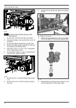
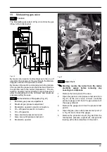
Removal of the flow switch group and
d.h.w. circuit filter
Warning: isolate the boiler from the mains
electricity supply before removing any
covering or component.
1
Remove the front panel of the case and empty the
d.h.w. circuit.
2
Remove the flow switch sensor (see section
14.4).
3
Unscrew the body 2(Fig. 61) and extract the flow
switch group.
4
To remove the filter from the flow switch group
separate the filter 9 from the threaded ring
(Fig. 61) by levering it.
5
Reassemble the parts following the removing se-
quence in reverse order.
14.6
Flow limiter
The M96.24SM/... model is factory fitted with a 10 litre/
min. flow limiter.
If on the M96.28SM/... and M96.32SM/... model the flow
rate of the d.h.w. circuit is too high, it is possible to limit
it by installing a flow limiter. The following sizes are avail-
able:
Nominal flow rate (litres/min)
Colour
10
Yellow
12
Brown
14
Pink
To install the threaded ring with the flow limiter:
1
Remove the flow switch group as explained in the
section 14.5.
2
Remove the filter from the flow switch group.
3
Unscrew the threaded ring 7 (Fig. 61) and re-
move it from the body 2.
4
Reassemble the group following the above se-
quence in reverse order.
Содержание GARDA HE M96.24SM/B2
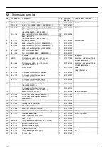
Страница 41: ...Short spare parts list 39 P5 1 2 6 4 5 7 3 8 14 17 12 19 21 22 23 25 26 13 15 24 16 18 9 10 11 9 20 27...
Страница 42: ......
Страница 43: ......


