


23
11
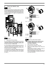
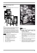
Modulating gas valve
11.1
Function
The Modulating gas valve
A
in Fig. 46 controls the gas
inflow to the boiler burner.
A
Fig. 46
By means of an electric command given to the on---off
operators the passage of the gas through the Modula-
ting gas valve can be opened or closed.
By means of an electric command given to the modula-
tion operator the pressure can be varied and therefore
the gas flow rate to the burner (modulation). The mo-
dulation operator has mechanical components which
allow the adjustment of the minimum and maximum
pressure exiting the valve.
11.2
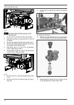
Nomenclature of the parts (Fig. 47)
1
Minimum gas pressure adjustment
2
Maximum gas pressure adjustment
3
Modulation operator’s electric connectors
4
On---off operators electric connector
5
On---off operators
6
Gas valve inlet pressure test point
7
Gas valve outlet pressure test point
8
Modulation operator
5
8
3
7
4
1
2
6
Fig. 47
11.3
Adjustment
Warning: isolate the boiler from the mains
electricity supply before removing any
covering or component.
1
Remove the front panel of the case.
2
Open the gas valve inlet pressure test point (6 in
Fig. 47) at the valve input, connect a suitable
pressure gauge and check the gas pressure of
the supply network.
3
Remove the gauge and close the pressure test
point 6.
4
Open the gas valve outlet pressure test point (7
in Fig. 47) and connect the gauge;
5
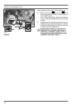
Remove the protection cap
B
(Fig. 48) from the
mechanical pressure adjustment components
levering with a flat screwdriver in the slots
C
.
Содержание GARDA HE M96.24SM/B2
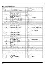
Страница 41: ...Short spare parts list 39 P5 1 2 6 4 5 7 3 8 14 17 12 19 21 22 23 25 26 13 15 24 16 18 9 10 11 9 20 27...
Страница 42: ......
Страница 43: ......


