


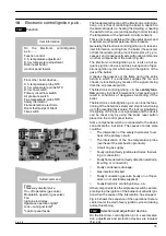


Electronic control/ignition p.c.b.
17
75
˚
C
Fig. 31
Normally, the result of the comparison between these
two signals directly operates the adjustment elements
of the gas valve modulation device, adjusting the useful
output generated in order to stabilize the temperature
of the exiting water.
If during the d.h.w. mode operation, the temperature of
the primary circuit goes over 75
°
C, the useful output is
automatically reduced so that the primary circuit can-
not reach excessive temperatures.
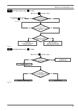
The control sequences in
function and in
func-
tion are illustrated in detail in sections 10.10 and 10.11.
10.4
Operation lights
The Electronic control/ignition p.c.b. is provided with
three lamps (L.E.D. indicators) 10 in Fig. 29 that give
optical information during the operation of the boiler.
The green lamp on the left gives information whether
the boiler is in stand---by mode or during the normal
operation of the boiler.
The following table gives the relationship between the
lamp indication and its meaning.
A short pulse every 4 seconds
Boiler in stand---by condition.
(function control in
position).
Anti---freeze system active.
1 second ON 1 second OFF
Boiler ON condition
(function control in
or
position)
With the boiler switched ON (
or
) all the lamps
(10 in Fig. 29) are activated.
The following table gives the relationship between each
of the possible lamp combinations and their meaning.
Normally operating boiler
(see the previous table for details)
C.h. operation
D.h.w. operation
Frost protect operation
D.h.w. operation
Excessive temperature on primary circuit
Faulty c.h. temperature probe NTC
Faulty d.h.w temperature probe NTC
Faulty flue temperature probe NTC
Faulty primary circuit
(no water or absence of flow)
Faulty air pressure switch
Lack of burner ignition (no ignition signal from
the full seqence ignition device)
Safety thermostat lock out
Flue temperature probe NTC lock out
Lack of power supply or fauly electronic
control p.c.b. *
Faulty Electronic control/ignition p.c.b.. *
Lamp
OFF
Lamp
ON
Flashing lamp, alone
or simultaneously
with an other lamp.
Flashing lamp,
alternate with
another lamp.
* These conditions are normal only for a short time when the
power supply is applied to the boiler.
If permanent they indicate a faulty p.c.b.
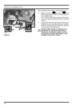
10.5
Setting the boiler control function modes
It is possible to select the various boiler control function
modes by using the function selector knob A and the
D.h.w. temperature control knob B (Fig. 32).
During the function modes setting, the boiler does not
operate.
C
E
D
A
B
Fig. 32
Содержание GARDA HE M96.24SM/B2
Страница 41: ...Short spare parts list 39 P5 1 2 6 4 5 7 3 8 14 17 12 19 21 22 23 25 26 13 15 24 16 18 9 10 11 9 20 27...
Страница 42: ......
Страница 43: ......


