

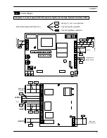
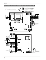


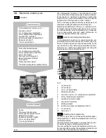


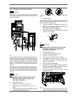


Electronic control p.c.b.
19
A short pulse every 4 seconds
Boiler in stand---by condition.
(function control in
position).
Anti---freeze system active.
1 second ON 1 second OFF
Boiler ON condition
(function control in
or
position)
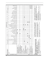
With the boiler switched ON (
or
) all the lamps
(7 in Fig. 29) are activated.
The following table gives the relationship between each
of the possible lamp combinations and their meaning.
Normally operating boiler
(see the previous table for details)
C.h. operation
D.h.w. operation
Frost protect operation
D.h.w. operation
Excessive temperature on primary circuit
Faulty c.h. temperature probe NTC
Faulty d.h.w temperature probe NTC
Faulty primary circuit
(no water or absence of flow)
Lack of burner ignition (no ignition signal from
the full seqence ignition device)
Ignition gas pressure adjustment
Minimum gas pressure adjustment
Lack of power supply or fauly electronic
control p.c.b. *
Fauly electronic control p.c.b. *
Lamp
OFF
Lamp
ON
Flashing lamp, alone
or simultaneously
with an other lamp.
Flashing lamp,
alternate with
another lamp.
* These conditions are normal only for a short time when the
power supply is applied to the boiler.
If permanent they indicate a faulty p.c.b.
10.5
Dip---switch selectors
The function selectors 8 (Fig. 29 and Fig. 32) are micro-
switches with which it is possible to select the various
boiler control function modes.
In Fig. 32 the selectors are illustrated in the configur-
ation in which the boiler is set in the factory (natural gas
boiler).
ON (1)
OFF (0)
1 2 3 4
8
Gas conversion
Ignition gas pressure adjustment
Reignition frequency
Minimum gas pressure adjustment
Fig. 32
f
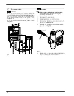
Selector 1
This forces the boiler to operate at the minimum gas
pressure in order to allow the adjustment of the mini-
mum gas pressure at the burner (on the modulation op-
erator of the gas valve).
After any adjustment operation the selector has to be
brought back to the normal position (ON).
f
Selector 2
This selects the boiler functions on the basis of the type
of gas used.
It allows the selection of the maximum supply current
given to the modulator device.
To set selector 2 correctly follow the table in Fig. 33.
Gas supply
Position of selector
Approx. Max current
through the modu-
lator device
Natural gas
On
120 mA
L.P.G.
Off
165 mA
Fig. 33
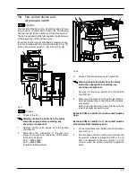
f
Selector 3
This forces the functioning of the boiler in order to allow
the optimal gas pressure at the burner to be adjusted
during the ignition phase.
The adjustment (see section 10.7) is done by means
of the potentiometer ”10” marked “ACC” (Fig. 29 on
page 17).
After the adjustment operations bring the selector back
to the normal position (ON).
gas pressure calibration
Normal
ON (1)
OFF (0)
Fig. 34
f
Selector 4
This allows you to select the minimum time that must
pass between two ignitions of the burner in c.h. func-
tion.
30 sec.
3 min.
ON (1)
OFF (0)
Fig. 35


