background image

Website:-www.bholanath.in

E-mail id:[email protected]

BHOLANATH PRECISION ENGINEERING PVT. LTD.

Page | 6

Wiring Notes

To prevent noise incurred in PUL/DIR signal, pulse/direction signal wires and motor wires
should not be tied up together. It is better to separate them by at least 10 cm, otherwise the
disturbing signals generated by motor will easily disturb pulse direction signals, causing
motor position error, system instability and other failures.

If a power supply serves several drivers, separately connecting the drivers is recommended

instead of daisy-chaining.

It is prohibited to pull and plug connector P2 while the driver is powered ON, because there is
high current flowing through motor coils (even when motor is at standstill). Pulling or
plugging connector P2 with power on will cause extremely high back-EMF voltage surge,
which may damage the driver.

Switch Choice:

1.Microstepping choice:

SW 6

off

on

off

on

off

SW 7

off

off

on

on

off

SW 8

off

off

off

off

on

Micro

200

400

800

1600

3200

2.Current choice

::::

SW 1

off

on

off

on

off

on

off

on

off

on

SW 2

off

off

on

on

off

off

on

on

off

off

SW 3

off

off

off

off

on

on

on

on

off

off

SW 4

off

off

off

off

off

off

off

off

on

on

Current

(A)

2

2.5

3

3.5

4

4.5

5

5.5

6

6.5

SW5:-OFF- Half Current, ON- Full Current.

Default setting is OFF i.e. Half Current. Full current to be used for increasing torque if required and for

holding torque operations. At full current motor and driver temperature will rise, kindly arrange external
cooling.

Note:-Any DIP Switch Setting other than above

Current:-The 0.5 A current will be set.

Microstep:-3200 microstep will be set.

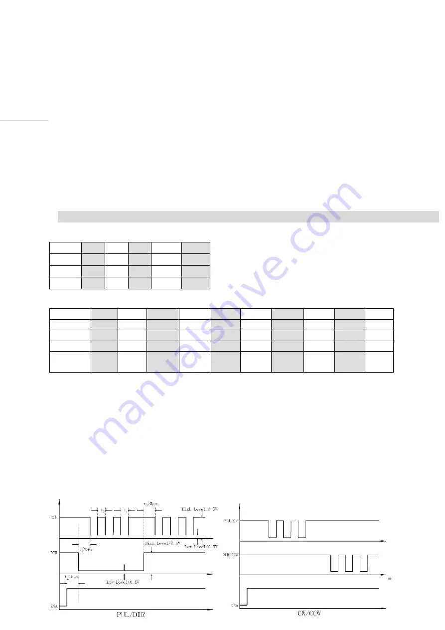
4.Sequence Chart of Control Signals

In order to avoid some fault operations and deviations, PUL, DIR and ENA should abide by

some rules, shown as following diagram

:

Содержание BH-SMART-6A

Страница 1: ...User s Manual For BH SMART 6A Micro Stepping Driver NOTE This driver is suitable for Nema 23 24 34 and 6 5 Amp model of Nema 42 stepper motors...

Страница 2: ...6A 6 Amp DRIVE HAVING INBUILT RPM DIRECTION CONTROL BY ROTARY SWITCH WITH ON OFF SWITCH BHOLANATH 1 DC power input 20VDC 72VDC 2 Output current 2A 6 5A 3 Micro stepping 200 400 800 1600 3200 4 Protec...

Страница 3: ...5 Wiring Notes 6 Switch Choices 6 4 Sequence Chart Of Control Signals 6 5 Calculation of pulse frequency 7 Frequency With Different RPM At 400 Micro Step 7 Frequency With Different RPM At 800 Micro S...

Страница 4: ...current and short circuit protection Low temperature rise smooth motion Pulses Response Frequency Can Reach 200KHz Support NPN PNP Pulse Direction Input Applications Suitable for a wide range of step...

Страница 5: ...ULT SIGNAL POSITIVE SUPPLY EXTERNAL FAULT FAULT SIGNAL STATUS OUTPUT EMMITER FOLLOWER Connector P2 Configurations Pin Function Details V DC POWER SUPPLY AC POWER SUPPLY GND GROUND A A MOTOR PHASE A B...

Страница 6: ...on will cause extremely high back EMF voltage surge which may damage the driver Switch Choice 1 Microstepping choice SW 6 off on off on off SW 7 off off on on off SW 8 off off off off on Micro 200 40...

Страница 7: ...ULATION OF PULSE FREQUENCY F RPM X MICRO STEP 60 If Need 60 RPM at 400 Micro Step Half Step Default Setting Then Frequency 60X400 60 400Hz TABLE a Frequency With Different RPM At 400 Micro Step RPM 60...

Страница 8: ...desired This configuration is also referred to as full chopper In full coil mode the motors should be run at only 70 of their rated current to prevent overheating 6 lead motor full coil higher torque...

Страница 9: ...rent surge If SMPS power supplies such as most switching supplies are indeed used it is important to have large current output rating to avoid problems like current clamp On the other hand if Linear s...

Страница 10: ...Check the motor wiring Motor or drive failure Replace the motor or drive Motor rotates in Motor phases connected in Reverse the phases line the wrong reverse direction Wrong I p direction signal Chan...

Страница 11: ...ts wiring Motor doesn t run motor without holding torque RESET signal is effective when offline Make RESET ineffective Motor doesn t run but Without input pulse signal Adjust PMW signal level maintain...

Страница 12: ...PRECISION ENGINEERING PVT LTD Page 12 10 FAULT OUTPUT Connection OR FAULT FAULT V GND FAULT O P STATUS O P FAULT FAULT GND V FAULT O P STATUS O P R R NOTE Maximum Current through the Fault Switch Is...

Страница 13: ...Website www bholanath in E mail id support bholanath in BHOLANATH PRECISION ENGINEERING PVT LTD Page 13 11 Circuit connections Of BH SMART 6A With BH SDC 01 SDC 02...

Страница 14: ...in E mail id support bholanath in BHOLANATH PRECISION ENGINEERING PVT LTD Page 14 12 Circuit Connections Of BH SMART 6A With PLC This is a Tentative connection Guideline for driving the Drive from Any...

Страница 15: ...may need this documentation to refer back to at a later date and these details will greatly assist our Technical Support staff in determining the problem should you need assistance Many of the proble...

Отзывы: