14
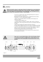
Fig. 7
Fig. 8
5.6.4 Stretching of the drive chains
After the first operation hours you possibly experience some extent of
release of the drive chain that will then need to be restretched.
Stretching is accomplished by first removing the safety guard on it
(Pos.1 - Fig. 9). Then slightly realease the fixation screws on the
mount (Pos. 2 - Fig. 9) and finally access the chain and start stret-
ching it by means of the
special adjustment screw (Pos. 4).
Adjust the chain so that you can still provoke some extent of deflec-
tion by applying one finger tip pressure in the middle. Then make the
PTO shaft turn and check for troublefree and effortless turning.
Properly stretched chains can still be deflected by 1-3 mm by app-
lying your maximum hand force in the middle of the distance between
sheaves.
1
The brake is engaged by means of a nut (3) and a nut (4). When the brake is engaged the lever (1)
shifts into its position EIN (Fig. 7).
First adjust the nut (3) using an open-end spanner until the nut stands approx 5 mm away from the
lever. Then adjust nut (4) till the sliding plate underneath the nut projects 3-4 mm out out of the
winch frame. If you cannot reach the required brake force, repeat the same steps tightening the nut
by further turning it to the right side.
Excessive brake force will cause troublesome unwinding procedures. In this case release the nut by
slightly turning it to the left.
4
1
3
2
Fig. 9
3
3
Содержание FSW 3.5 M
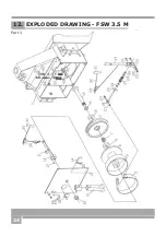
Страница 24: ...24 12 EXPLODED DRAWING FSW 3 5 M Part 1...
Страница 25: ...25 Part 2...
Страница 29: ...29...
Страница 30: ...30...
Страница 31: ...31...


