background image

BGS technic KG

Bandwirkerstr. 3

D-42929 Wermelskirchen

Tel.: 02196 720480

Fax.: 02196 7204820

[email protected]

www.bgstechnic.com

© BGS technic KG, Copying and further use not allowed

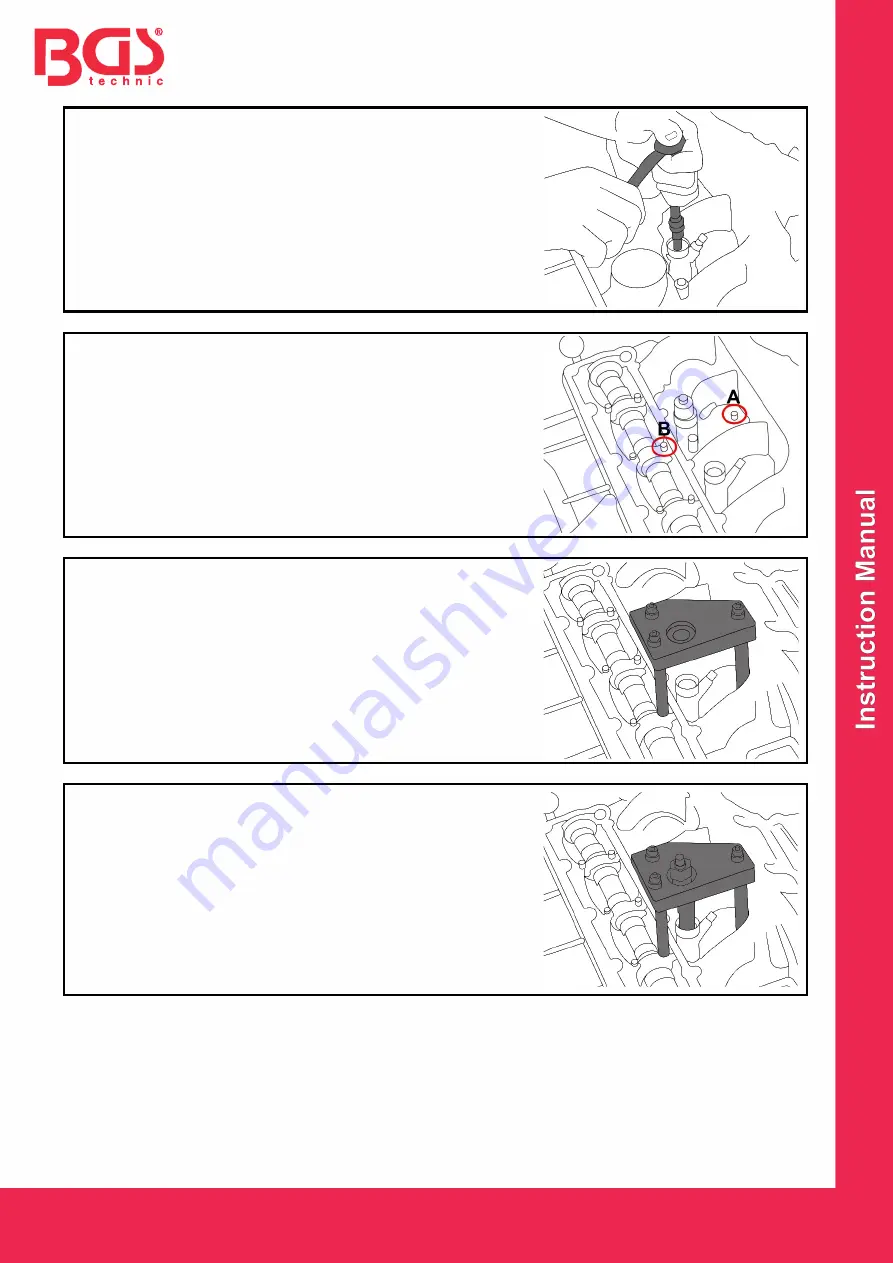
Remove the ring nut with the internal hexagon socket.


Loosen the screws of cylinder head cover and remove the 

cover. 


Loosen and remove the screws of the intake manifold (

A

) and 

the bearing cover (

B

).


Place the support bolts in the holes in the intake manifold and 

in the  screw of the bearing cover , as shown in the 

illustration.


Screw the pulling spindle through the bridge into the injector. 


Screw the nut onto the pulling spindle. 


Turn the nut of the pulling spindle with a wrench while holding 

the spindle on the hexagon with a suitable wrench. 


The injector is pulled out by turning the nut clockwise. 


As soon as the nut can be turned easily, the injector with pull-

out unit can be removed by hand. 


Содержание 8349

Страница 1: ...ungsanleitung bei wenn Sie das Produkt an Dritte weitergeben VERWENDUNGSZWECK Dieser Werkzeugsatz erm glicht eine Demontage von HDI Injektoren Bosch und Siemens ohne Demontage des Zylinderkopfes und i...

Страница 2: ...erviceliteratur Fetten Sie immer das Spindelgewinde ehe Sie das Werkzeug verwenden Halten Sie Kinder und unbefugte Personen vom Arbeitsbereich fern Lassen Sie Kinder nicht mit dem Werkzeug oder dessen...

Страница 3: ...rdeckel B entfernen St tzbolzen wie in der Abb zu sehen in die Bohrungen der Ansaugkr mmer und Lagerdeckelschraube aufsetzen Zugspindel durch die Br cke in den Injektor schrauben Mutter auf die Zugspi...

Страница 4: ...structions in a safe and dry location for future reference Enclose the operating instructions when handing over the product to third parties INTENDED USE This tool set enables HDI injectors Bosch and...

Страница 5: ...ays grease the spindle thread before using the tool Keep children and unauthorized persons out of the work area Do not allow children to play with this tool or its packaging and keep this tool out of...

Страница 6: ...ake manifold A and the bearing cover B Place the support bolts in the holes in the intake manifold and in the screw of the bearing cover as shown in the illustration Screw the pulling spindle through...

Страница 7: ...sent mode d emploi au produit si vous le transmettez des tiers UTILISATION PR VUE Ce jeu d outils permet un d montage des injecteurs HDI Bosch et Siemens sans d montage de la culasse et convient pour...

Страница 8: ...c de la graisse et avant d utiliser l outil Maintenez l cart les enfants et toutes les autres personnes non autoris es de la zone de travail Ne permettez pas aux enfants de jouer avec l outil ou son e...

Страница 9: ...support comme le montre l illustration dans les per ages des vis du collecteur d aspiration et du couvercle du roulement Visser la broche de traction travers le pont dans l injecteur Visser l crou sur...

Страница 10: ...nes y la anulaci n de la garant a Guarde estas instrucciones en un lugar seguro y seco para futuras consultas Incluya el manual de instrucciones si entrega el producto a un tercero USO PREVISTO Este j...

Страница 11: ...l veh culo para obtener informaci n t cnica como los valores de par de apriete las instrucciones de desmontaje montaje etc Engrase siempre la rosca del husillo antes de usar la herramienta Mantenga a...

Страница 12: ...la tapa de las v lvulas Retire el tornillo del colector de admisi n A y la tapa del cojinete B Coloque los pernos de soporte en los agujeros de los pernos del colector de admisi n y de la tapa de coj...

Отзывы: