


4.5
Removing the Convection Fan.
4.5.1
Remove the burner from the combustion chamber as described in
section 4.1.
4.5.2
Ensure that the electrical supply to the fire is isolated.
4.5.3
Remove the retaining nuts that hold the convection fan assembly to
the base of the combustion chamber, remove electrics cover and
disconnect the wiring from the V module.
4.5.4
Lift the convection fan assembly clear, remove fan cover and disconnect
to fan unit, remove screws from underside of fan plate and lift fan unit
clear.
4.5.5
Re-assemble in reverse order.
4.6
Replacing the Batteries in the Handset.
4.6.1
Remove and re-fit the new 3 off AAA batteries by removing the cover on
the back of the handset.
4.7
Checking for Flue Debris.
4.7.1
Remove the burner assembly as detailed in section 4.1 and remove fan
plate assembly.
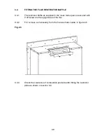
4.7.2
Locate the removeable backplate on the rear face of the firebox at the
bottom.
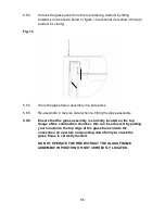
4.7.3
Remove the 2 screws that hold the removeable backplate on the rear
face of the firebox.
4.7.4
Remove any debris.
4.7.5
Replace the removeable backplate on the rear face of the firebox.
4.7.6
Re-assemble in reverse order and carry out a gas tightness test.
42