35
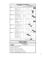
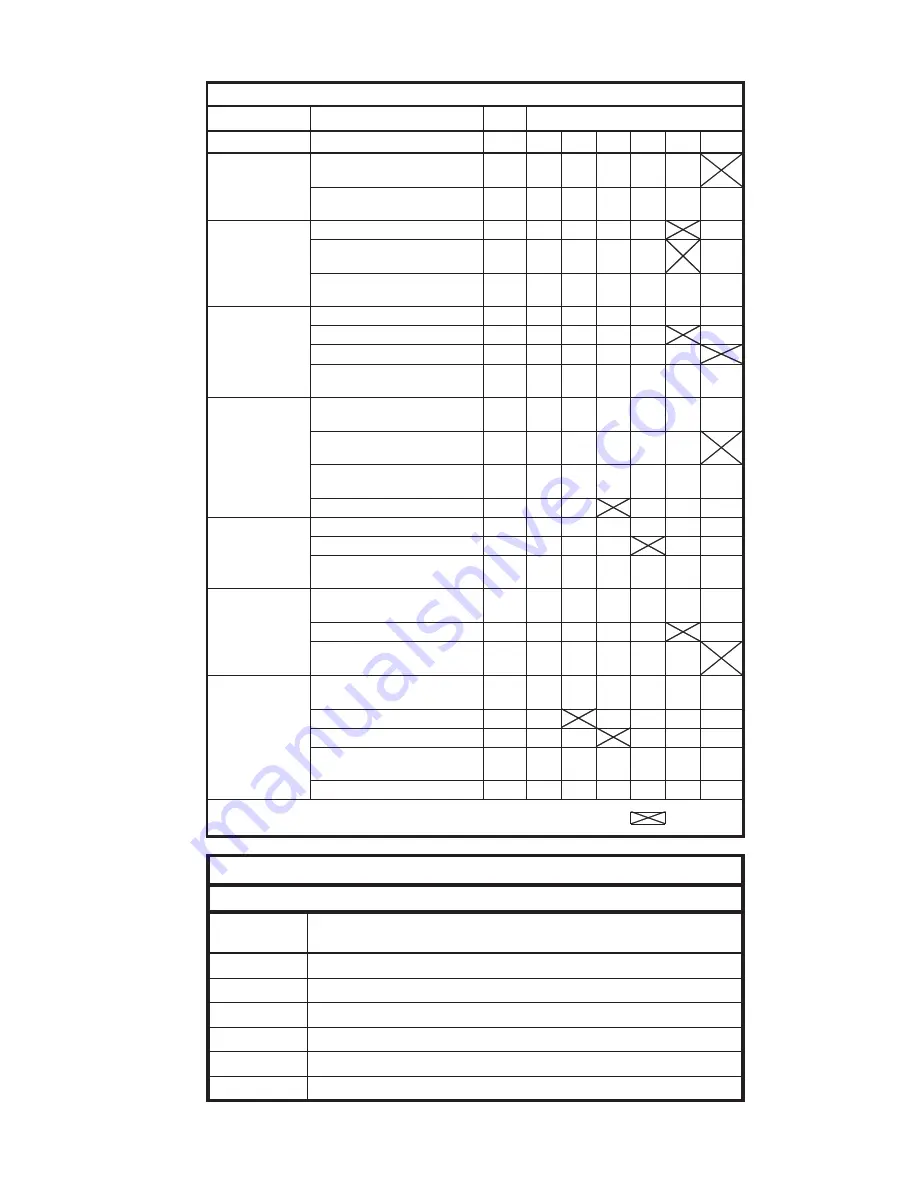
MAINTENANCE SCHEDULE
Genie CE
HD
RECOMMENDED SERVICE INTERVALS
(HOURS)
DAILY
50
100 250 400 750 1,000
ELECTRIC
Check tightness of electric contacts
and fuses
0
0
0
,
1
0
0
1
Check state of electric cables
crossing the machine
400
SOLUTION TANK
0
5
7
Y
L
I
A
D
r
e
tl
if
n
o
it
u
l
o
s
f
o
s
s
e
l
n
a
e
l
c
k
c
e
h
C
Check water valves and hoses to the
brush head
100
750
Check all water connection from the
tank to the brushes
250
RECOVERY TANK
Check cleanless of the tank
DAILY
0
5
7
Y
L
I
A
D
m
e
t
s
y
s
t
a
o
lf
d
n
a
r
e
tl
if
k
c
e
h
C
0
0
0
,
1
Y
L
I
A
D
s
e
s
o
h
n
i
a
r
d
d
n
a
m
u
u
c
a
v
k
c
e
h
C
Check vacuum gasket and drain
hoses plugs
100
BRUSH HEAD
Check splash guard and right brush
inclination
100
Check tightness and of the belts and
state of bearings
250
1,000
Check brush attachments (rust,
ruined parts, cracks)
250
0
5
2
0
5
s
e
h
s
u
r
b
e
h
t
f
o
r
a
e
w
k
c
e
h
C
BRUSH MOTOR
0
0
1
t
e
l
n
i
g
n
il
o
o
c
r
i
a
f
o
s
s
e
l
n
a
e
l
c
k
c
e
h
C
0
0
4
0
5
2
s
e
h
s
u
r
b
n
o
b
r
a
c
k
c
e
h
C
Check Amps consuption and noise
level
1,000
VACUUM MOTOR
Check noise level and cleanless of
the inlet hose
100
0
5
7
0
5
2
s
e
h
s
u
r
b
n
o
b
r
a
c
k
c
e
h
C
Check vacuum performance, replace
if necessary
400
1,000
SQUEEGEE
Check cleanless of the blades and
squeege regulation
DAILY
0
0
1
0
5
e
d
a
l
b
k
c
a
b
f
o
r
a
e
w
k
c
e
h
C
0
5
2
0
0
1
e
d
a
l
b
t
n
o
rf
f
o
r
a
e
w
k
c
e
h
C
Check squeege structure and
machine support
400
0
0
4
e
l
b
a
c
g
n
it
fi
l
d
n
a
r
e
v
e
l
k
c
e
h
C
Suggested replacement
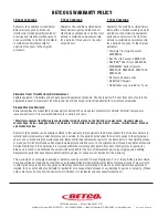
WEAR ITEMS
Genie CE
HD
PART
NUMBER
DESCRIPTION
E81608
Aggressive Brush
E82408
Pad Holder
E82526
Brush, Med. Scrubbing
E83863
Brush, General Scrubbing
E83869
Squeegee Blade, Rear, Shore 33
E83870
Squeegee Blade, Front, Shore 33
Содержание GENIE CE HD APS
Страница 18: ...18 SQUEEGEE SYSTEM PARTS DIAGRAM 6 3 4 13 14 12 11 5 18 1 7 10 8 8 18 15 16 5 9 5 17 2 9 ...
Страница 20: ...20 SQUEEGEE YOKE PARTS DIAGRAM 4 2 11 13 10 6 7 5 2 6 7 9 14 12 8 3 1 ...
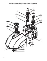
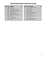
Страница 24: ...24 SOLUTION AND RECOVERY TANKS PARTS DIAGRAM 10 17 8 19 9 11 19 1 18 12 14 15 5 3 7 20 4 2 13 21 22 6 16 ...
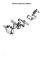
Страница 28: ...28 ELECTRIC SYSTEM PARTS DIAGRAM 2 6 4 3 5 3 7 10 2 9 1 8 ...
Страница 30: ...30 ELECTRICAL DIAGRAM ...
Страница 31: ...31 ...

