


4
INTRODUCTION
betamotor.com
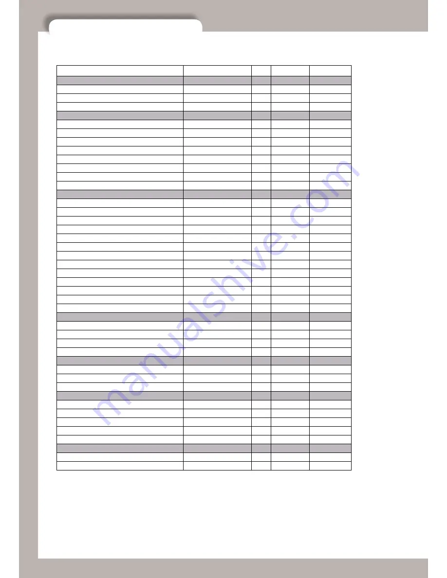
FIXING
PART
PCS
THREAD LOCK TORQUE [NM]
ENGINE FIXING
Engine front fixing
10x1,5L127 [5.8]
1
25
Engine back fixing
10x1.25L100 [5.8]
1
30
Cylinder head fixing
8x1.25L55 [8.8]
1
30
FRAME PARTS
Engine arms to frame
8x1.25L16 [8.8]
4
25
Engine bumper (front fixing)
8x1.25L16 [8.8]
2
20
Engine bumper (back fixing)
8x1.25L20 [8.8]
2
30
Filter box support brackets
8x1.25L20s [10,9]
2
X
25
Footrest brackets
8x1.25L25 [8.8]
4
X
30
Engine retaining plates
6x1L50 [8.8]
2
15
Regulator support
5x0.8L8 [8.8]
2
5
Fixing screws for oil tank and regulator
5x0.8L12 [8.8]
1
5
SWING ARM
Swing arm to frame/engine
16x1,25L255 [5.8]
1
50
Shock absorber to frame
10x1,25L50 [8.8]
1
45
Shock absorber to lever
10x1,25L45 [8.8]
1
45
Lever to swing arm
10x1.5L75 [10,9]
1
45
Connecting rods to lever
10x1.5L125 [10.9]
1
45
Connecting rods to frame
8x1,25L42 [10,9]
2
30
Stand to swing arm
6x1L20 [8.8]
2
X
10
Sliding block chain tightener to swing arm
8x1.25L12s [8.8]
1
10
Chain tightener spring fixing
5x0.8L20 [8.8]
1
5
Chain guide shoe rubber (upper)
6x1L35 [8.8]
1
10
Chain guide shoe rubber (lower)
5x0.8L8 [8.8]
1
5
Sprocket cover
5x0.8L8 [8.8]
2
5
Pipe fastening clamps
5x0.8L6 [8.8]
2
5
FRONT FORK
Triple fork clamp (fixing tubes)
6x1L25 [8.8]
10
10
Handlebar to triple fork camps
8x1.25L30 [8.8]
2
30
Fork adjusting ring nut
Speciale
1
25
Head tube nut
18
1
25
HANDLEBAR DEVICES
Throttle control
4x0.7L12 [8.8]
2
3
Clutch master cylinder
4x0.7L12 [8.8]
2
3
Brake master cylinder
5x0.8L15 [8.8]
2
3
BRAKES
Front brake caliper (upper)
8x1.25L55 [8.8]
1
X
23
Front brake caliper (lower)
8x1.25L35 [8.8]
1
X
23
Rear brake master cylinder to frame
6x1L16 [8.8]
2
12
Brake pedal
8x1.25L20 [8.8]
1
X
10
Brake disk cover
4x0.7L14 [8.8]
2
3
EXHAUST
Silencer to frame (upper)
6x1L25 [8.8]
1
10
Silencer to frame (lower)
6x1L10 [8.8]
1
10
FASTENING BOLT TORQUE SETTINGS - FRAME
Содержание EVO 4t
Страница 1: ...WORKSHOP MANUAL...
Страница 2: ......
Страница 3: ...WORKSHOP MANUAL 2009...
Страница 4: ......
Страница 6: ......
Страница 79: ......