background image

betamotor.com

2

ENGLISH

Operation and use

51

A

ON

OFF

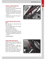
STARTING THE ENGINE WHEN HOT

1 Put the gearbox in neutral.
2  Operate the hot start by pulling outward 

the knob C (the red one) 

3  WITHOUT opening the throttle, press the 

kickstart  lever  progressively  downwards, 
avoiding violent strokes, to the bottom of 
its travel.

4  Release the hot start after the engine has 

run for some instants

STARTING WHEN THE BIKE HAS FALLEN 

OVER

If  the  bike  falls  over,  the  carburettor  float 
bowl may empty.
1  Open manually the fuel tap by turning the 

lever A clockwise (ON)

2  Put the gearbox in neutral.
3  Operate the Hot Start knob (C).
4  WITHOUT opening the throttle, press the 

kickstart  lever  progressively  downwards, 
avoiding violent strokes, to the bottom of 
its travel.

5 Close the fuel tap.

ADVANCE MAP CHANGE SWITCH

Using the switch shown in the figure, it is 
possible  to  choose  between  two  different 
map for spark advance.
With the switch in position 1, 

“soft”

 map is 

selected, more suitable for slippery terrain 
and for a softer engine response.
With the switch in position 2, 

“hard”

 map 

is selected, for a more aggressive engine re-
sponse: more suitable for dry conditions.  

1

2

Содержание EVO 4T 2012

Страница 1: ......

Страница 2: ...t hour of break in to check the tightness of all fasteners paying particular attention to the following Footrest brackets Front and rear brake discs Wheel spokes Shock absorber bolt and rear linkage Engine bolts Rear sprocket Exhaust bolts ...

Страница 3: ...on circuit 55 Engine oil 56 Brake master cylinder fluid 59 Brakes circuit bleeding 60 Clutch master cylinder fluid 62 Clutch circuit bleeding 62 Fork oil 63 Sparkplug 64 Air filter 65 Ignition generator check 66 Front brake 67 Rear brake 68 Coolant 69 Rear suspension linkage 70 Checks after cleaning 70 Scheduled maintenance 71 CHAPTER 4 ADJUSTMENTS INDEX OF TOPICS Brake adjustment 73 Clutch adjust...

Страница 4: ......

Страница 5: ...Chapter 1 General information INDEX OF TOPICS Main parts Vehicle identification details Engine identification details Console and controls Technical details Wiring scheme ...

Страница 6: ...tails A are stamped on the right hand side of the headstock ENGINE IDENTIFICATION DETAILS Engine identification data B is stamped in the area shown in the figure In order to read it correctly it is necessary to remove the silencer and disconnect the regulator connector CONSOLE AND CONTROLS 1 Clutch lever 2 Front brake lever 3 Throttle twistgrip 1 2 3 5 4 4 Tasto spegnimento motore 5 Tasto accensio...

Страница 7: ...ic forks with 38 mm stanchions rebound and spring preload adjustment Fork oil capacities right leg 370 cc left leg 350 cc Rear suspension progressive hydraulic monoshock with rebound and spring preload adjustment Front and rear brake discs disc with hydraulic control Engine type Single cylinder 4 stroke 4 valve head SOHC ZD3E77 bore x stroke 77x53 6 mm 250cc 84x53 6 mm 300 cc displacement cm3 249 ...

Страница 8: ... not run the engine with the voltage regulator connected to the electrical gene rator without having connected the vehicle wiring harness central system Doing so could cause damage to the regulator itself betamotor com ENGLISH General information 1 ...

Страница 9: ...49 INDEX OF TOPICS Filling the fuel tank Start up Advance map change switch Break in Checks and maintenance before and after off road use Recommended lubricants and liquids Chapter 2 Operation and Use ...

Страница 10: ... vehicle is on its side can lead to a lowering of the fuel level in the carburettor float bowl making the bike hard to start in this case open manually the fuel tap by tur ning the lever A clockwise ON Once the engine has started reclose the fuel tap Starting the engine from cold 1 Put the gearbox in neutral 2 Operate the choke lever B black knob by pulling it outwards 3 WITHOUT opening the thrott...

Страница 11: ... may empty 1 Open manually the fuel tap by turning the lever A clockwise ON 2 Put the gearbox in neutral 3 Operate the Hot Start knob C 4 WITHOUT opening the throttle press the kickstart lever progressively downwards avoiding violent strokes to the bottom of its travel 5 Close the fuel tap ADVANCE MAP CHANGE SWITCH Using the switch shown in the figure it is possible to choose between two different...

Страница 12: ...lts CHECKS AND MAINTENANCE BEFORE AND AFTER OFF ROAD USE To avoid unpleasant surprises while operating the vehicle we recommend that you perform a series of checks and maintenance jobs both before and after use In fact dedicating just a few minutes to these checks and jobs will not only make riding safer but can save you time and money Proceed as follows Tyres Check the pressure general condition ...

Страница 13: ...isted in the table TYPE OF PRODUCT TECHNICAL SPECIFICATIONS Engine oil Bardahl XT C60 15W50 Brake and clutch fluid Bardahl brake fluid dot 4 Fork oil Idemitsu oj racing 01 Bel ray mc 10sae 5 Grease for linkages Bardahl outboard grease Coolant Bardahl permanent Filter oil Bardahl oil filter Note When changing the fluids we recommend that you adhere strictly to the table shown ...

Страница 14: ...Brakes circuit bleeding Clutch master cylinder fluid Clutch circuit bleeding Fork oil Air filter Ignition generator check Sparkplug Front brake Rear brake Rear suspension linkage Coolant Checks after cleaning Scheduled maintenance Chapter 3 Maintenance and checks betamotor com ...

Страница 15: ...h two pipes one of which 6 takes it to the crankshaft to lubri cate the roller bearing on the crankpin the other 7 whose flow is regulated by a cali brated hole on the cylinder base gasket 8 feeds the valvegear 9 The oil then returns to the base of the crank chamber from the piston the conrod assembly and the cylin der walls and is drawn in by the scavenge pump 10 through the mesh filter 11 It is ...

Страница 16: ... veral minutes and then switch it off Place the bike on a flat surface in such a way that it is perfectly vertical Wait a few minutes and then check the oil level in the sightglass located in the clutch casing right hand side of the engine The level must be between the limits indicated in the picture If necessary remove the oil filler plug and top up the level N B Running the engine with too littl...

Страница 17: ...ine has reached operating temperature switch the bike off and stand it upright Unscrew the oil drainplug and let all the oil flow out into a drain pan Thoroughly clean the magnet on the drainplug to get rid of the metallic impurities that it has collected Unscrew the plug in the left hand casing and use pliers to extract the filter Clean it carefully and blow it through with compres sed air Check ...

Страница 18: ... com 3 ENGLISH Maintenance and checks 58 Execute same procedure for the filter loca ted on the right side of crankcase Put a drawn pan under the engine closer to the paper filter cover and then unscrew the cover ...

Страница 19: ... and refill with 0 9 litres of engine oil BARDHAL XTC60 15W50 Finally tighten the oil filler plug A to 10 Nm BRAKE MASTER CYLINDER FLUID Front brake Use the sight glass A to check the brake fluid level There must always be enough brake fluid for the level to be visible in the sight glass If there is not enough the fluid must be brought up to the correct level To do this refill the reservoir by uns...

Страница 20: ...es through the tube repeat the above operations until the fluid that comes out is free of air Note During this operation it is important that you top up the master cylinder reservoir continually to compensate for the fluid which has been pum ped out Remove the small tube Refit the rubber cap Note Handle brake fluid with care being corrosive it can damage painted or plastic parts irrepa rably B A W...

Страница 21: ...hold the pedal down Unscrew the bleed nipple allowing the fluid to flow through the tube Reclose the bleed nipple and release the pedal If bubbles of air are visible through the tube repeat the above operations until the fluid that comes out is free of air Note During this operation it is important to top up the master cylinder reservoir continually to compen sate for the fluid which has been pump...

Страница 22: ...he bleed nipple C Take off the clutch fluid reservoir cover Fit one end of a small transparent tube over the bleed nipple D and insert the other end into a container Pump 2 3 times with the lever and hold the lever down Unscrew the bleed nipple allowing the fluid to flow through the tube Reclose the bleed nipple and release the lever If you can see air bubbles through the tube repeat the above ope...

Страница 23: ...g the cartridge located under the fork leg and extract the cartridge 7 Drain the fork leg and cartridge comple tely of oil 8 Refit the cartridge to the fork leg tighte ning the retaining bolt then refill with oil OJ01 thus charging the cartridge up to the level shown in the diagram with fork leg fully compressed 9 Refit the cap to the damper rod tighten the locknut and screw the cap onto the stanc...

Страница 24: ...that may remain between the fork seal and the dust cover by removing the dust cover Note Recommended tightening torque 7 8 9 1 Nm Sparkplug Keeping the sparkplug in good condition helps to reduce fuel consumption and keep the en gine running optimally To check it just pull off the plug cap and un screw the sparkplug Check the gap between the electrodes with a feeler gauge it should be 0 6 0 7 mm I...

Страница 25: ...nd water 3 Dry it 4 Moisten it with filter oil removing any ex 5 cess so that it does not drip If necessary clean the inside of the filter 6 box as well Proceed with reassembly We recommend 7 first assembling the frame on the filter Note If the filter is very dirty wash it first with petrol then with shampoo and water If the filter is damaged replace it immediately Caution After every intervention...

Страница 26: ...k may also be performed with the generator mounted on the motorbike or on the engine Disconnect the black 12 way connector between the generator and the CDI Disconnect the white 2 way connector between the generator and the wiring Use a multimeter to check that the resi stances read between the terminals shown below fall within the prescribed range BLACK WHITE 320 ohm 15 Pick Up RED BLUE 15 ohm 15...

Страница 27: ...g the check Pad replacement To replace the pads proceed as follows Remove the disc cover and the caliper by 1 unscrewing the two screws A and loo sening screw B Take off split pin C 2 Unscrew screw B 3 Remove the pads D and replace them 4 For reassembly proceed in reverse order 5 On the screws A it is advisable to use an appropriate medium resistance lo cking agent Note Pay particular attention to...

Страница 28: ... replace the pads immediately Note Check the brakepads at the intervals given in the table on page 71 Replacing the brakepads To replace the pads proceed as follows Remove the wheel Remove the caliper from the swingarm Unscrew screw A Remove the pads and replace them For reassembly proceed in reverse order On screw A it is advisable to use an appro priate medium resistance locking agent If the bra...

Страница 29: ... through the radiator Undo screw F located on the left hand side of the cylinder head until the coolant comes out of the bleed hole Tighten the bleed screw and continue pouring the liquid into the radiator until it reaches the flared section in proximity to the filler cap The capacity of the circuit is given in the table on page 47 Use the fluids recommen ded in the table on page 53 Caution To pre...

Страница 30: ...ushings with an inner diameter of 8 mm and the special M screws Secure the relay arm to the swingarm using the bushings with heads which are 2 5 mm thick and the M 10x75 screw and to the shock absorber M10x45 screw Then mount the connecting rods on the relay arm using the remaining bushings and the M10x125 screw Note The prescribed tightening torques are 4 5 kgm for screws A B C and E and 3 0 kgm ...

Страница 31: ...ngine oil S I S S Engine oil main filter S S S Engine oil mesh filters P P P Coolant I I I I Brakes I I I S Steering gear I I I I Vehicle nuts and bolts I I I I Cilinder Head nuts and bolts I I I Valve clearance I I Piston rings S Piston I S I Inspection checking tightening replacement as required P Cleaning S Replacement pay particular attention to the nuts and bolts securing the progressive leve...

Страница 32: ...djustment Clutch adjustment Tickover adjustment Throttle free clearance adjustment Steering play check and adjstment Chain tension Front suspension adjustment Rear shockabsorber adjustment Chapter 4 Adjustments betamotor com ...

Страница 33: ...of the lever use adjuster screw A It is advisable to leave a minimum of play Rear brake The rear brake is disc type with hydraulic control You can adjust the pedal height using adju sters B and C We recommend that you leave a minimum of free clearance CLUTCH ADJUSTMENT The only adjustment that can be made on the clutch adjusting the position of the clutch lever E To make this adjustment use adjust...

Страница 34: ...ulates the base position of the throttle valve Throttle free clearance adjustment To adjust the tension of the throttle cable use adjuster B If this amount of adjustment is insufficient use adjuster C on the throt tle cable itself CHECKING AND ADJUSTING STEERING CLEARANCE Check the steering head tube clearance on a periodic basis moving the forks back wards and forwards as shown in the figure If a...

Страница 35: ...eration Tighten nut E To re secure proceed in reverse order CHAIN TENSION For a longer life of the final drive chain we suggest you to check its tension pe riodically Always clean off dirt deposits and lubricate it If the free clearance in the chain exceeds 20 mm it needs tensioning as follows Slack off nut A Adjust with lever B Adjust with the same lever on the opposi te side taking it to the sam...

Страница 36: ...ve ride back off the com pression adjustment screw A For a more controlled ride tighten the compression adjustment screw A Note For the standard adjustment position the screw at 12 clicks from fully open Periodically clean the working area of the buffer as follows Lower remove the buffer using a small screwdriver and blow compressed air by means of the milling on the spring spacer Always ensure th...

Страница 37: ...Chapter 5 What to do in an emergency betamotor com ...

Страница 38: ...d operate the kick start lever repeatedly Drained floatbowl Operate the manual tap as described on page 50 THE ENGINE MISFIRES Sparkplug with incorrect electrode gap Set the electrode gap correctly See note on page 64 Sparkplug dirty Clean or replace the sparkplug Earthing fault Check insulation at kill switch POOR FRONT BRAKING Pads worn greasy or vitrified Follow procedure on page 67 Air or mois...

Отзывы: