


12
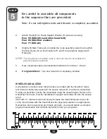
Be careful to assemble all components
in the sequence they are presented.
note:
Do not fully tighten bolts until the unit is completely assembled.
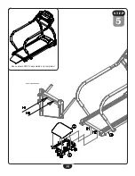
A.
Connect Cable A1 (88) to Cable A2 (89).
B.
Secure Right Upright Post (F) to Main Frame (A) by using:
two 48 (m10x25 round allen head bolt)
Four 65 (M10.5 flat washer)
two 70 (m10 nut)
NoTe:
Pay attention to not pinch Cable A1 (88) or Cable A2 (89) when securing
Right Upright Post (F) to Mainframe (A).
Assistance may be required.
C.
Slide Vertical Bar (H) into Right Upright Post (F) as shown in the diagram using:
one 51 (m8x15 round allen head bolt)
One 66 (M8.5 flat washer)
D.
Secure Left Upright Post (G) to Main Frame (A) by using:
two 48 (m10x25 round allen head bolt)
Four 65 (M10.5 flat washer)
two 70 (m10 nut)
E.
Attach Vertical Bar (H) to Left Upright Post (G) using:
one 112 (m8x45 round allen head bolt)
One 66 (M8.5 flat washer)
s T e p
2
Содержание BFT50
Страница 1: ...BFT50 O w n e r s M a n u a l v 091709...
Страница 11: ...11 S T EP 1 Above shows STEP 1 assembled and completed...
Страница 13: ...13 S T EP 2 Above shows STEP 2 assembled and completed...
Страница 15: ...15 S T EP 3 Above shows STEP 3 assembled and completed...
Страница 17: ...12 17 S T EP 4 Above shows STEP 4 assembled and completed...
Страница 19: ...19 S T EP 5 Above shows STEP 5 assembled and completed...
Страница 39: ...39 BFT50 Wiring Diagram...
Страница 40: ...40 Exploded View Diagram...
Страница 41: ...41 Exploded View Diagram...
Страница 42: ...42 Notes...
Страница 43: ...43 Notes...