


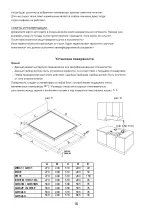


Installation area
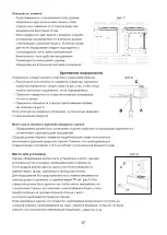
Fig.9
In the room where the gas appliance is installed,
there must be a sufficient natural air supply to
allow the gas to burn correctly (in conformity of currents laws).
The natural flow of air must take place through an
opening made on an outside wall of the room
and having a working section of at least 100 cm
2
(A).
In the case of appliances without safety
valves, this opening must have a minimum
working section of 200 cm
2
(fig.9).
This opening must be made in such a way that it cannot be obstructed from inside or outside.
It should be positioned near floor level, preferably on the side opposite the fume exhaust devices.
If it is not possible to make the necessary openings, the air can be supplied from an adjacent, suitably
ventilated room, as long as this room is not a bedroom, a dangerous area or a lowpressure area.
Removal of combustion fumes
Combustion fumes produced by gas appliances must be removed by means of a hood connected
directly either to an exhaust duct or to the outside (fig.7).
If a hood cannot be installed, an electric extractor fan must be fitted to the outside wall or the window.
This electric extractor fan must have a sufficient capacity to guarantee a change of air of the
kitchen of at least 3-5 times its volume.
Components shown in fig.7:
A Opening for air supply
C Hood for exhaust removal of combustion fumes
E Electric extractor fan for removal of combustion fumes
Connection to gas supply
Before installation, make sure the type and pressure of the local gas supply are compatible with the
cooktop settings.
To do this, check the data on the appliance data plate on the cooktop as well as on this handbook.
The gas connection must be carried out by a qualified technician in compliance with local current laws.
If using metal hoses, ensure these do not come into contact with any movable parts and are at no point
crushed. Carry out the connection in such a way as does not cause any stress whatsoever on the appliance.
The gas supply connector is threaded G½”.
After connection operations, check for leaks using a soapy solution.
Electrical connection
Before connecting the appliance to the electricity supply, check that the voltage corresponds to that on the
data plate and that the power supply cable is suitable for the appliance load also stated on the data place.
If the appliance is connected directly to the mains, fit an all-pole disconnect switch with minimum
contact gap of 3 mm, adequate for the appliance load and complying to regulations.
The plug used must support the power of work of the appliance.
7
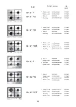
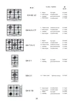
Содержание BH 31 IX
Страница 1: ...BUILT IN COOKTOPS INSTRUCTIONS BOOKLET ...
Страница 2: ......
Страница 12: ...10 ...
Страница 13: ... 90 396 73 23 2006 95 89 336 2004 108 93 68 89 109 1935 2004 11 ...
Страница 14: ... 3 Y 90 1 2 3 4 5 6 7 8 9 3 3 12 ...
Страница 15: ... 4 5 15 1 4 5 15 13 ...
Страница 16: ... 4 5 1 2 140 x 350 1 6 1 10 200 240 160 200 160 R A 140 200 240 220 280 SR 60 TR 200 180 14 ...
Страница 17: ...0 0 1 2 3 4 5 6 8 9 6 1 10 200 C 5 10 3 4 1 2 7 8 15 ...
Страница 19: ... 10 7 8 5 8 2 3 100 2 200 2 9 UNI CIG 7129 7 9 17 ...
Страница 20: ... 9 3 5 UNI CIG 7129 9 A C E UNI CIG 7129 7131 UNI CIG 9891 2 ISO R7 ISO R228 3 90 20 0 75 2 18 ...
Страница 21: ... N L J G30 G31 3 0 75 2 3 1 2 3 1 5 2 19 ...
Страница 22: ... 20 ...
Страница 28: ...26 ...
Страница 29: ...27 ...
Страница 30: ...28 ...
Страница 31: ......
Страница 32: ...H01A5121 ...


