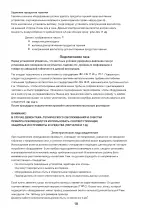
BEST Chef BH 31 IX Скачать руководство пользователя страница 10

Warnings:

 - 

Do not use reducers, adapters or switches for connection to the mains, since these

could overheat and cause burns.

 - 

Earth connection is required by law. The manufacturer declines all liability

resulting from failure to observe this regulation.

If the power cable must be replaced, use a cable having identical characteristics to the original

supplied by the manufacturer, suitable for the load and temperature (type T90°C). This is available

from After-sales service. Furthermore, the end of the power cable to be connected to the appliance

must have the Yellow-Green earth conductor 20 mm longer than the other conductors.

The cable must support the load of the appliance.

Refer to the table below for the size of the power cable

Only with gas burners

With electric plate(s) <= 1000W

With electric plate(s)  >1000W <2000W

With electric plate(s) >=2000W

Should it be necessary to replace the supply cord,

connect the wire in accordance with the following colours/codes:

BLUE

NEUTRAL (N)

BROWN

LIVE (L)

YELLOW-GREEN

EARTH ( -  )

 - 

Check wether there is a omnipolar switch available on the domestic line which is compliant with

current standards laws.

Otherwise, place a device easily reachable between the appliance and the electricity line.

 - 

If the cable result damaged, it must be quickly replaced with a new one by a qualified technician

or call the After-Sales service.

If a different type of gas from the one indicated on the rating plate is used, the injectors must be replaced.

If spare injectors are not supplied with the appliance, they are available from the After-sales service.

For the choice of replacement injectors, refer to the injectors table at the end of this booklet.

The injectors are identified by their diameter, which is expressed in hundredths of mm, stamped on

the body of the injector itself.

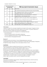
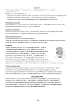
Replacing the injectors

 - 

Remove the grids and burner caps from the cooktop

 - 

Using a socket wrench, replace the injectors “J” 

with the suitable ones for the gas used

 - 

Replace the burners

The burners do non require primary air adjustment.

Adjustment of minimum setting

After replacing the injectors, light the burner and remove the knob. Turn the tap to the minimum setting

and insert a screwdriver in the rod: tighten to reduce the flame, loosen to increase the flame. (fig.)

For gas G30/G31, tighten the adjustment screw fully
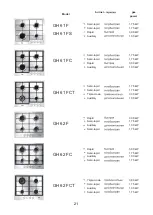
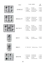
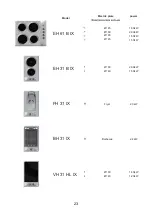
Cooktop type

Wire size

Ø0,75 mm

2

Ø1,50 mm

2

Ø2,50 mm

2

Ø2,00 mm

2

ADJUSTMENT TO DIFFERENT TYPES OF GAS

8

Содержание BH 31 IX

Страница 1: ...BUILT IN COOKTOPS INSTRUCTIONS BOOKLET ...

Страница 2: ......

Страница 3: ...r to identify the model that corresponds your appliance These informations together with the instructions and the illustrations in the following paragraphs will show you the characteristics of your appliance An Example Legend Trade Mark Corresponding model Technical code Customer code Power inputs Voltage and frequency data Country of target market and gas details Gas burners power Gas burners con...

Страница 4: ... without pan stands Warning The ignition device must not be used for more than 15 seconds If after this length of time the burner does not light or if it goes out again accidentally wait 1 minute before trying to ignite it again Grids The panstand grids are designed to make the appliance easy and safe to use Always check the panstand grids are properly positioned before using the appliance Further...

Страница 5: ...meter such as covers the entire burner surface Switching on the hotplates To switch on the electric hotplate turn the knob to the desired position Numbers 1 to 6 or 1 to 10 depending on whether the cooktop is fitted with a power switch or regulator indicate the settings in progressing temperature See Table When the electric hotplate is in operation an indicator led on the control panel lights up U...

Страница 6: ...is off The indicator lamp turn off automatically once the temperature of the cooking zone falls below 70 C Barbecue To turn on the element turn the knob clockwise this sets the relative thermostat with settings from 1 to 10 The pilot light turns on to show that the element is in operation It is normal for some types of lamp to show a little light even when the plates are not working Using the grid...

Страница 7: ...any worktop as long as it is heat resistant minimum temperature of 90 C The dimensions of the hole to be made in the worktop and the minimum distances between rear and side walls and those above the appliance are shown in figures 5 and 6 Fig 5 GH61B GH61BS GH62F GH61F GH62LC GH62LC 290 585 585 595 290 290 490 480 480 480 490 490 270 560 560 560 270 270 510 500 500 510 510 510 E D A B C fig 6 560 4...

Страница 8: ...e cooktop in the housing proceed as follows Position the special gasket supplied C along the outer perimeter of the worktop following the diagram shown in fig 5 so that the ends of the gasket meet exactly without overlapping Position the cooktop into the worktop taking care to ensure it is placed exactly in the centre Fix the cooktop to the worktop using the special brackets supplied A as shown in...

Страница 9: ...ty to guarantee a change of air of the kitchen of at least 3 5 times its volume Components shown in fig 7 A Opening for air supply C Hood for exhaust removal of combustion fumes E Electric extractor fan for removal of combustion fumes Connection to gas supply Before installation make sure the type and pressure of the local gas supply are compatible with the cooktop settings To do this check the da...

Страница 10: ...th current standards laws Otherwise place a device easily reachable between the appliance and the electricity line If the cable result damaged it must be quickly replaced with a new one by a qualified technician or call the After Sales service If a different type of gas from the one indicated on the rating plate is used the injectors must be replaced If spare injectors are not supplied with the ap...

Страница 11: ...panstand grids of the cooktop are dishwasher safe Stainless steel panstand grids may take on a bluish tinge on parts around the burners as a result of the high temperatures This effect can be reduced by using commercially available steel wool pads Burners The burners comprising two parts can be removed and cleaned using suitable detergents After cleaning dry the burners thoroughly and reposition t...

Страница 12: ...10 ...

Страница 13: ... 90 396 73 23 2006 95 89 336 2004 108 93 68 89 109 1935 2004 11 ...

Страница 14: ... 3 Y 90 1 2 3 4 5 6 7 8 9 3 3 12 ...

Страница 15: ... 4 5 15 1 4 5 15 13 ...

Страница 16: ... 4 5 1 2 140 x 350 1 6 1 10 200 240 160 200 160 R A 140 200 240 220 280 SR 60 TR 200 180 14 ...

Страница 17: ...0 0 1 2 3 4 5 6 8 9 6 1 10 200 C 5 10 3 4 1 2 7 8 15 ...

Страница 18: ...62F GH61F GH62LC GH62LC WH31 GH31 270 490 50 FH31 40 BH31 270 490 510 290 5 6 A B C D E 510 290 270 490 510 EH31B VH31HL 270 490 510 585 290 150 290 45 595 35 560 480 500 585 35 560 480 500 35 560 480 510 685 35 560 480 510 16 ...

Страница 19: ... 10 7 8 5 8 2 3 100 2 200 2 9 UNI CIG 7129 7 9 17 ...

Страница 20: ... 9 3 5 UNI CIG 7129 9 A C E UNI CIG 7129 7131 UNI CIG 9891 2 ISO R7 ISO R228 3 90 20 0 75 2 18 ...

Страница 21: ... N L J G30 G31 3 0 75 2 3 1 2 3 1 5 2 19 ...

Страница 22: ... 20 ...

Страница 23: ... 1 75 kW Semi rapid 1 75 kW Triple crown 3 30 kW Auxiliary 1 00 kW Rapid 3 00 kW Semi rapid 1 75 kW Auxiliary 1 00 kW Semi rapid 1 75 kW Rapid 3 00 kW Semi rapid 1 75 kW Auxiliary 1 00 kW Semi rapid 1 75 kW Triple crown 3 80 kW Semi rapid 1 75 kW Auxiliary 1 00 kW Semi rapid 1 75 kW GH 62 FC GH 62 FCT GH 61 F GH 61 FS burner GH 61 FC GH 61 FCT GH 62 F Model 21 ...

Страница 24: ... kW Auxiliary 1 00 kW Semi rapid 1 75 kW Rapid 3 00 kW Semi rapid 1 75 kW Triple crown 3 30 kW Auxiliary 1 00 kW Semi rapid 1 75 kW Rapid 3 00 kW Auxiliary 1 00 kW Semi rapid 1 75 kW Semi rapid 1 75 kW Rapid 3 00 kW Auxiliary 1 00 kW GH 61 B GH 62 LC Triple crown GH 62 LCT GH 72 LC GH 31 WH 31 Model burner 3 30 kW 22 ...

Страница 25: ...ower 1 00kW 2 00kW 1 50kW 1 50kW 2 00kW 1 50kW 1 80kW 1 20kW Model Electric plate EH 61 B IX EH 31 B IX Ø145 Ø180 Ø180 Ø145 VH 31 HL IX Ø180 Ø140 2 3kW BH 31 IX 2 4kW FH 31 IX Fryer Barbecue Ø180 Ø140 23 ...

Страница 26: ...Brown Blue Connection to gas supply Union Gasket Pipe or hose FH31IX BH31IX Electrical wiring diagram Yellow Green E D F 24 ...

Страница 27: ...ar Burners G20 G30 G20 G30 Max kW Min kW Min kW Auxiliary Semi rapid Rapid Triple crown 0 44 0 30 0 72 0 97 Gas type Gas power Ø inyector Gas pressure 0 37 0 50 0 65 0 50 1 00 1 70 0 90 0 91 0 85 1 75 3 00 3 30 1 50 1 15 1 24 0 75 25 ...

Страница 28: ...26 ...

Страница 29: ...27 ...

Страница 30: ...28 ...

Страница 31: ......

Страница 32: ...H01A5121 ...

Отзывы: