Besam AAE977 Скачать руководство пользователя страница 7

Ultraview US23-0640-09 


07-30-09 


      V4

© Copyright 2009 Besam US Inc.  May not be reprinted without permission               


                        7

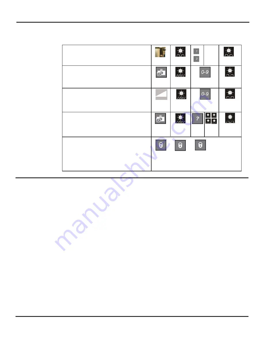
Adjusting Settings with Remote Control

Every programming session must begin by unlocking the sensor. Thereafter, a program 

setting may be altered by pressing the desired function key, followed by the desired value 

for that function. When all programming is complete, press the lock key twice to retain 

settings. Use the following as a guide:

Setting up the Sensor with the Remote Control


The sensors can be programmed with the aid of the remote control.  


To do so, perform the following:


1.

With the P1 and P2 harnesses connected, apply main power to the Unislide control.


2.

Unlock P1 with the remote control (be certain only P1 is unlocked):


a.

Press the Unlock button (the LED will flash red quickly)


b.

Press 0 (as a function key)


c.

Press 1 (the LED will flash red slowly indicating communication)


d.

Press lock twice (this will program the chosen sensor to a ‘P1’ designation)


3.

Unlock P2 with the remote control:


a.

Press the Unlock Button (the LED will flash red quickly)


b.

Press 0


c.

Press 2 (this will program the chosen sensor to a P2 designation)


d.

Press lock twice


4.

To check the sensor’s designation, unlock the sensor, and then press the number 1 or 2.  


The LED will flash red slowly when the correct number is entered.  After complete,    


press lock twice.


5.

Shut off main power to the Unislide - wait 5 seconds.


6.

Re-apply power.


7.

Unlock P1 (press unlock then 1).


8.

Press magic wand on the remote control.


9.

Press 0 - this will launch a set-up.  Keep traffic away from the sensor’s pattern.


a.

Sensor will flash red and green alternately


b.

Both sensors will automatically go through a set-up


c.

The door will open, then close while the LED is flashing (the sensors are 


learning the influence of the door) - this will take approximately 16 seconds


d.

To adjust properly, follow the instructions on page 5, section 5c

   Unlock the sensor to enter into adjustment session 
(if no access code has been entered). If a lock code is 
present: the “1” for P1 or “2”, for P2 must be entered, 
followed by the lock code.

To change the value of a parameter 
(ex. Automatic learn time)

… to change any other parameters 
(ex. Sensitivity)

To check the value of a parameter (ex. Automatic Learn 
Time)

Lock the adjustment session and go back to normal 
function

* the lock code may be one, two, three or four digits 

long.  If the lock code is less then 4 numbers, then the 

code must be followed by the lock button to lock the sen-

sor.

Press Unlock

key

RED LED

flashes

1=P1

or

2=P2

RED LED

flashes

Select

parameter to

change

RED LED

flashes quickly

Enter new

value

RED LED

flashes slowly

Select

parameter to

change

RED LED

flashes quickly

Enter new

value

RED LED

flashes slowly

Select

parameter to

check

RED LED

flashes quickly

Press

Question 

Mark

The number of 

green flashes

indicate the 

value of this

 parameter

RED LED

flashes slowly

...

Press lock key twice

or

+ lock code*

Содержание AAE977

Страница 1: ...0 09 07 30 09 V4 Copyright 2009 Besam US Inc May not be reprinted without permission 1 Complies with ANSI BHMA A156 10 Standard for Power Operated Pedestrian Doors UL325 Listed Besam UltraView Install...

Страница 2: ...r detection performance SPECIAL NOTE The Ultraivew works differently than the BEA Wizard When making changes to the Ultraview reference the Ultraview users guide If you inadvertently make changes base...

Страница 3: ...roduct conformity R TTE 1999 5 EC EMC 89 336 EEC FCC Interface Factory Installed Technology Microwave and microprocessor Transmitter frequency 24 125 GHz Transmitter radiated power 20 dBm EIRP Transmi...

Страница 4: ...connector on the Ultraview Interface Board Ultraview US23 0640 09 07 30 09 V4 Copyright 2009 Besam US Inc May not be reprinted without permission 4 MOUNTING SCREWS INFRARED LENS SHROUD SENSOR COVER U...

Страница 5: ...the push button is released Then repeat step 2 5 Mechanically adjust the presence field of each sensor for the installation a Launch a setup of the system by momentarily pressing and releasing the rig...

Страница 6: ...LENS FACTORY DEFAULT 6 6 W X13 75 D CHANGE PRESENCE LENS IF NEEDED REMOVE BEZEL OPTIONAL NARROW ANGLE ANTENNA ADJUST ANGLE BY TILTING MICROWAVE CELL 7 0 height 13 W X 6 6 D 6 6 W X 8 2 D Wide Narrow...

Страница 7: ...t off main power to the Unislide wait 5 seconds 6 Re apply power 7 Unlock P1 press unlock then 1 8 Press magic wand on the remote control 9 Press 0 this will launch a set up Keep traffic away from the...

Страница 8: ...rol 0 min 9 max default 7 Sensitivity Microwave Detection Mode 1 bidirectional mode 2 unidirectional mode 3 unidirectional mode with MTF Setup launch an assisted setup restore factory settings When re...

Страница 9: ...he door will not re cycle open at this time it will continue to close because the motion output is going to the Outer Impulse at the control box which has been ignored due to the 1 way traffic selecti...

Страница 10: ...eter being altered 1 flash means value 1 The right button enables selection of the parameter number being altered 1 for each press The left button enables alteration of the value 1 for each press EXAM...

Страница 11: ...resence If LED s are illuminat ing make sensor adjustments as necessary to eliminate unwanted detection Check angle and sensitivity for presence and motion see pg6 2 Check for moving objects in the pa...

Страница 12: ...pressing the reset button next to the 5 position switch 3 Select correct sensor with P1 1 Reset system to neutral 2 Power Off On by pressing the reset button next to the 5 position switch 3 Select co...

Страница 13: ...ows the User to toggle between STD and AUX The STD position is the default position The AUX position is selected for applications that require initial activation by the Knowing Act device only Thus wh...

Страница 14: ...cover position to the 1 way traffic mode The AUX input will not be acknowledged when placed in the STD position KNOWING ACT TO PUSH PLATES DRY CONTACT ONLY DIP SWITCH P1 P2 TO BREAKOUT SWITCHES 1 Wir...

Страница 15: ...activation regardless of door position 3 Setting the rotary switch to the OFF position will disable all inputs once the door is fully closed c Part Time 1 Way Security Day Night Mode Set STD AUX swit...

Страница 16: ...bottom guide assembly for proper adjustment and excessive wear 13 Check door closing speed and closing force 14 Check closing latch location 15 Check that door hold open time is 1 5 seconds or longer...

Отзывы: