


11
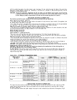
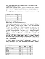
ROAST CHICKEN
235 (225)
4
40-45
FISH
200-225 (190-215)
3
15-25
PASTRY
FRUIT PIE
200 (210)
3
35-40
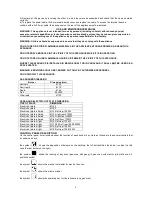
TEA CAKE
190 (180)
3
50-55
BRIOCHES
175 (165)
3
25-30
SPONGE CAKE
235 (225)
3
20
RING CAKE
190 (180)
3
30-40
SWEET PUFF PASTRIES
220 (210)
3
20
RAISIN LOAF
220 (210)
3
15-20
STRUDEL
180 (170)
3
15-20
SAVOIA COOKIES
190 (180)
3
15
APPLE FRITTERS
220 (210)
3
20
SAZOIARDI SANDWICH
220 (210)
3
20-30
TOAST SANDWICH
250 (240)
4
5
BREAD
220 (210)
3
30
PIZZA
220 (210)
3
20
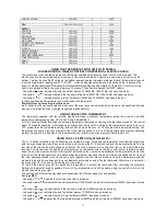
USING THE THERMOSTAT WITH SWITCH IN SERIES
(COOKERS WITH A SINGLE-CONTROL CONVENTIONAL ELECTRIC OVEN)
The electric oven is controlled by an electric thermostat combined with a switch used to turn on the elements. The
electric oven can be combined with an electric grill. The oven is heated by 2 elements: one on the top and one on the
bottom. Turning the knob (fig.27) turns on the bottom element and the top external elements while the thermostat is used
to set the temperature ranging from 50°C to 250°C. It can be adjusted using the scale indicated on the ring around the
knob. An orange light turns off indicating that the temperature setting has been reached. Therefore, it is normal for this
light to turn on and off while the oven is working. There are 3 fixed position beyond the 250°C settin g:
- the symbol or indicates the only the bottom element (1300W M6; 1800 W M9) has been turned on;
- the symbol or indicates that only the top external element (900W M6; 1200 W M9) has been turned on;
- the symbol or indicates that only the grill element (1500W M6; 1800W M9) has been turned on;
In these positions the temperature is not controlled by the thermostat.
Warning! Oven light running for static oven.
As for cookers with one control electric static oven, the oven lamp can be switched on thanks to the specific button and
also every time that the oven is ignited trought the relative selector.
USING THE ELECTRIC THERMOSTAT
The thermostat supplied with the relative models maintains a constant temperature inside the oven at a specific
temperature setting ranging from 50°C to 250°C.(fig .28A-28B-28C)
Turn the knob clockwise and align the selected temperature indicated on the ring with the index etched on the control
panel. Thermostat operation is indicated by an orange light which will turn off when the temperature inside the oven is
10°C greater than the temperature setting, and will turn on when the oven is 10°C less than the temper ature setting. The
thermostat can control the oven elements only if the relative switch is in one of the possible oven element operating
modes: if the switch is in position 0, the thermostat has not effect on the oven elements, which remain off.
USING THE 9 + 0 SWITCH (fig.29A-29B-29C)
The 9 + 0 switch installed in the multifunction oven models is used, along with the thermostat, to control the electric fan
and the oven elements since they can be turned on by turning the 9 + 0 switch knob and the thermostat knob. Turning
just one of the two knobs will not have any effect on the oven except to turn on the oven light or the electric fan when
inserted. The electric oven is heated by 4 elements: one on the bottom, two on the top or one circular; turning the switch
knob turns on the element relative to the symbol indicated on the ring but to be activated the thermostat knob must be
turned until the orange light turns on indicating that the element has been turned on. Placing the switch knob on any of
the nine operating modes turns on the oven light, together with the relative element. Once the temperature and the
elements to be used have been set, the oven elements are turned on and off by the thermostat; therefore, it is normal for
the orange light to turn on and off while the oven is working.
To turn off the electric oven set the switch knob to position 0 to prevent the thermostat from controlling the elements.
Setting the thermostat knob to position 0 turns off the elements but it is still possible, using the switch, to turn on the
electric fan and the oven light.
The switch has 9 different fixed positions corresponding to 9 different types of oven operation:
For type M6V
- the symbol or indicates that only the oven light is turned on;
- the symbol or indicates that the bottom element (1300W) and the top external element (900W) have been turned
on;
- the symbol or indicates that only the top external element (900W) has been turned on;
- the symbol or indicates the only the bottom element (1300W) has been turned on;
- the symbol or indicates that only the grill element (2000W) has been turned on;
- the symbol or indicates that the top external element (900W) and the grill element (2000W) have been turned on;
Содержание TU64C61DX
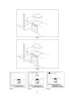
Страница 16: ...16 Fig 1 Fig 2 Fig 3 Fig 4 Fig 5 ...
Страница 17: ...17 Fig 6 Fig 7A Fig 7B Fig 8 Fig 9A Fig 9B Fig 10A Fig 10B ...
Страница 18: ...18 Fig 11A Fig 11B Fig 12 Fig 13 Fig 14 Fig 15 Fig 16 Fig 17 Fig 18 ...
Страница 19: ...19 Fig 19 Fig 20 Fig 21 Fig 22 A Fig 22 B Fig 22 C Fig 23 Fig 24A Fig 24B Fig 24C Fig 24D ...
Страница 20: ...20 Fig 25A Fig 25B fig 26a Fig 26b Fig 26c Fig 26d ...
Страница 21: ...21 Fig 27 Fig 28A Fig 28B Fig 28C Fig 29A Fig 29B Fig 29C Fig 30 Fig 31 Fig 32A Fig 32B Fig 32C ...
Страница 22: ...22 Fig 33 Fig 34 Fig 35 Fig 36 Fig 37 Fig 38 ...
Страница 24: ...310796 ...


