background image


7

2


e

g

a

P

Lighting & Shutdown Instructions 

-

Lighting

1.  Open manual gas supply valve (ensure gas supply lines have been purged). 
2.  Turn on switch to energize electric supply. 
3.  The electronic control module will time begin the ignition period in 3 seconds. 
4.  The gas valve will open and ignition spark will commence and continue for 20 sec. 
5.  If flame starts and “is detected”, flame will continue until turned off. 
6.  If no flame is detected, the gas valve will close after 20 sec. A “wait’ period commences and 

lasts approximately 5 sec. and a second trial for combustion commences. The electronic 

control will attempt three trials for ignition before locking out for approximately 1 hour at which 

time it will automatically try again. 

Electronic control of heater can be re-set by de-energizing and re-energizing electric power. 

-

Shut Down 

1.  Turn off power to electronic control. 
2.  For longer periods of shut down, also close manual gas supply valve. 

Note:

It is recommended to use a factory recommended “Hi-Lo switch” with this heater.  

March, 2013

BERNER PATIO+ Luminous

Содержание BPL-HAB20

Страница 1: ...er flammable vapours and liquids in the vicinity of this or any other appliance An LP cylinder not connected for use shall not be stored in the vicinity of this or any other appliance IMPORTANT OWNER...

Страница 2: ...March 2013 BERNER PATIO Luminous...

Страница 3: ...onal Low Clearance Ceiling Mounting Kit HAB M20 Only 15 Using Optional Low Clearance Ceiling Mounting Kit HAB M40 and M50 Only 16 Using Optional Low Clearance NON COMBUSTIBLE Ceiling Mounting Kits all...

Страница 4: ...rictly supervised when in the area of this heating appliance Playing or running around the structure should be strictly forbidden Clothing or other flammable materials should not be hung on or near th...

Страница 5: ...ndoor or outdoor installation Not for use in residential dwellings refer to Rating plate Gas Supply Lines Gas supply pipe sizing must be in accordance with the National Fuel Gas Code ANSI Z223 1 NFPA...

Страница 6: ...4 12 34 11 25 32 91 11 41 10 64 12 34 11 25 Model Model 32 52 47 06 Gas Connection High and Low Operation Lights Optional Electrical Connection Note Connections shown for all Models 5 41 Electrical Co...

Страница 7: ...closing its individual manual shutoff valve during any pressure testing of the gas supply piping system at test pressures equal to or less than psig 3 5 kPa Power Gas Specifications Gas Supply Natura...

Страница 8: ...8 e g a P Equipment Standard Equipment Included March 2013 BERNER PATIO Luminous BPL HAB20 BPL HAB40 BPL HAB50...

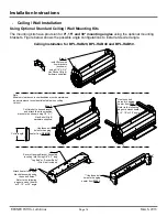
Страница 9: ...centres 3 8 X 3 Anchor Bolts minimum 4 per heater with minimum 16 0 mounting spacing on centres Optional Standard Ceiling Wall Mounting Kits Hanging Bracket Assembly QTY 1 Unistrut 18 0 Long QTY 2 Ex...

Страница 10: ...Shield QTY 1 Heat Shield Mounting Bracket QTY 4 Heat Shield QTY 1 Heat Shield Mounting Bracket QTY 4 Extension Arm Hanging Bracket QTY 2 Hanging Bracket Assembly QTY 1 Low Clearance Mounting Bracket...

Страница 11: ...ble materials for various installation configurations Additional clearance may be required for glass painted surfaces and other materials which maybe damaged by radiant or convective heat Combustible...

Страница 12: ...eld 30 Model Dim A Dim B Dim C Dim D Dim E Dim F Dim G Dim H 13 75 34 48 10 16 66 9 13 75 34 48 10 16 66 9 9 47 17 29 8 5 9 38 3 D B C F Less than 30 mounting angle Less than 30 March 2013 BERNER PATI...

Страница 13: ...ritical dimension watching for interference from overhead beams etc Figure below provides a general overview of the components utilized in the installation as well as their general relationship Cautio...

Страница 14: ...as per clearance to combustibles table when cutting Unistrut Step 2 Cut Unistrut to desired length and attach them to extension brackets as shown using 1 2 X 1 Hex Bolts Qty 8 hardware supplied Cut t...

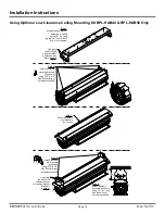
Страница 15: ...wn using 5 16 X 3 4 Hex Socket Qty 4 hardware supplied Step 1 Mount Low Clearance Brackets to ceiling using 3 8 X 3 long Lag Bolt or Anchor Bolt Qty 4 not supplied 31 0 Step 3 Slide Heat Shield over b...

Страница 16: ...ong Lag Bolt or Anchor Bolt Qty 4 not supplied Step 3 Slide Heat Shield over brackets as shown 9 00 Use these two bolt holes to attach bracket to extension arm refer to step 4 Step 4 Install Extension...

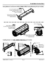
Страница 17: ...bolt holes Step 2 Attach heater to Brackets as shown using 5 16 X 3 4 long Hex Socket Qty 4 hardware supplied 3 00 Attach heater to hanging bracket assembly using these bolt holes Non Combustible Cei...

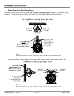
Страница 18: ...onfiguration Use these bolt holes when mounting heater from ceiling at any angle 0 15 30 15 30 Right side of bracket Left side of bracket Use these bolt holes when mounting from wall at any angle 0 15...

Страница 19: ...clearance to combustibles 9 00 Minimum Ceiling Mount Distance Minimum Ceiling Mount Distance using Optional Shield Use these bolt holes for positioning at this angle 3 00 Note Other clearances must be...

Страница 20: ...t to 13 75 to achieve the minimum clearances to combustibles for this model Use these bolt holes for positioning at this angle Use these bolt holes for positioning at this angle Cut unistrust to 10 00...

Страница 21: ...ount Distance using Optional Shield Use these bolt holes for positioning at this angle Note Other clearances must be maintained as per clearance to combustibles table Use these bolt holes for position...

Страница 22: ...es must be maintained as per clearance to combustibles table Cut unistrust to 13 75 to achieve the minimum clearances to combustibles for this model Use these bolt holes for positioning at this angle...

Страница 23: ...ada CAN CGA B149 1 and B149 2 National Gas and Propane Installation Code latest editions Do not use high pressure above psig to test the gas supply system with the appliance connected Failure to compl...

Страница 24: ...grams below for guidance on electrical wiring of heaters If any of the original wire as supplied with the heater must be replaced it must be replaced with wiring having a rating of at least 105 C temp...

Страница 25: ...115 VAC Grounded Supply Ensure A Good Ground Source Manual Line Switch with Hi LO wiring diagram Two Stage Switch wiring diagram 24 Volt AC Supply 24 Volt Transformer Ensure A Good Ground Source 115...

Страница 26: ...s heater is NOT approved for any indoor Residential application If in doubt of your application consult with your local fire marshal or gas authority having jurisdiction Indoor spaces include but are...

Страница 27: ...etected the gas valve will close after 20 sec A wait period commences and lasts approximately 5 sec and a second trial for combustion commences The electronic control will attempt three trials for ign...

Страница 28: ...ct the igniter Replace igniter if there is excessive wear or erosion breakage or other defects The reflector sections may be cleaned by wiping with a damp cloth Annually verify hose gas supply in heat...

Страница 29: ...HG035 1 Ignition Wire not shown Electronic Ignition Module Gas Valve NAT Burner Assembly HAB M20 Burner Assembly HAB M40 and HAB M50 3 4 5 SE004 SE009 20VA 24V Transformer not supplied SE010 6 40VA 24...

Страница 30: ...warranty does not cover any shipping installation or other costs incurred in the repair or replacement of the product No materials will be accepted for return without authorization This warranty will...

Отзывы: