


Page 4/7
03-2015
WLAN Access-Point (order no. 4582)
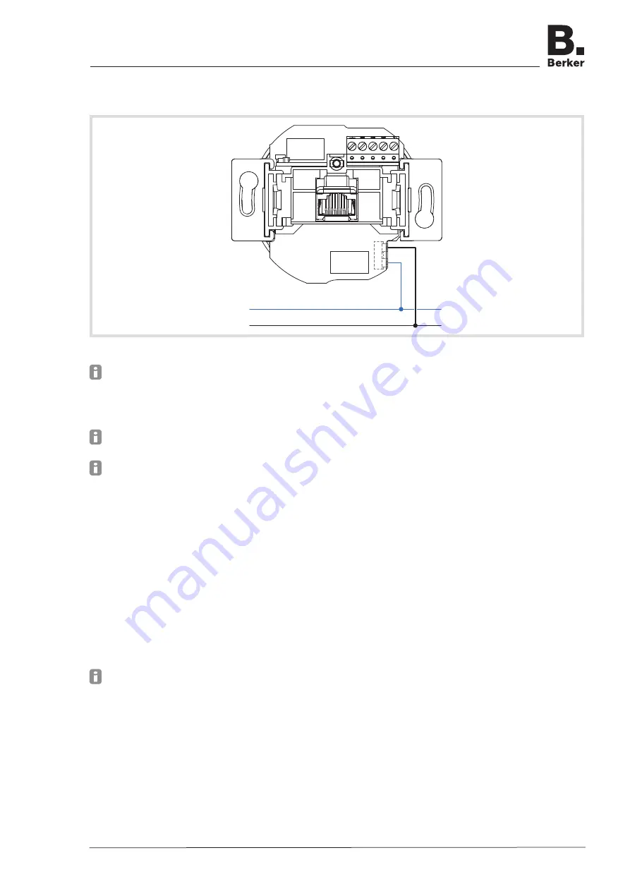
Connect device to power supply
N
L
(8)
Figure 3:
Connection supply voltage
Live cables and network cables must always be laid separately from each other to the wall
box.
Run the mains cable into the wall box from below.
Strip cable adequately and connect cables to the plug-in terminals (8) (Figure 3).
To release the plug-in terminal, press down the retaining lug e.g. using a small flat-bladed
screwdriver and pull out the cables.
The power supply of active components, such as from this device or from a PC, must be
disconnected from the other consumers in order to prevent any disruptions in the network.
For this purpose, use a separate circuit secured by an automatic cutout or circuit breaker as
well as appropriate overvoltage protection if necessary. The circuit and connected socket
outlets must be labelled clearly e.g. with
EDV
.
Connect network cable
Run the mains cable into the wall box from above.
Shorten the cable to a length of approx. 90 mm from the bottom of the wall box.
Strip the cable to approx. 80 mm. When doing so, keep the pair shielding and twist of the
pair and wires as far as possible.
Twist the outer shielding
S
and affix it in a conductor sleeve (1 mm²) if necessary.
Pull off 5pole terminal block (1) from the device and lay the wires according to the prescribed
colour coding (Table 2). Cut off wires not required.
The assignments on the terminal block must match those of the patch panel in the network.
Mount terminal block (1) onto the contact pins (3) (Figure 4).
Mount the device into the wall box.
Unscrew cover.
Switch ON power supply.
Device with the factory settings is ready for operation. A configuration for individual settings
can be made.
WLAN Access-Point flush-mounted
6LE001255A


