background image

9

Maintenance

Motor Replacement

For Reference Numbers [shown as (3) or (5)], refer to the 
Exploded View, Figure 14, for BVM2 and BVM4 Series 
Models, Figure 16 for BVMI/X2 and BVMI/X4 Models, 
Figure 15 for BVM8 and BVM16 Series Models, and 
Figure 17 for BVMI/X8 and BVMI/X16 Series Models.

 Risk of electric shock. Can shock, burn or 

kill. Disconnect all power to the pump before servicing 
or working on pump. Make sure that power is locked out 
and that pump cannot be accidentally started.
1.  Disconnect the power to the pump motor.
2.  Close the nearest suction and discharge valves.
3.  Remove the coupling guards (4) by prying them 

loose with a screw driver.

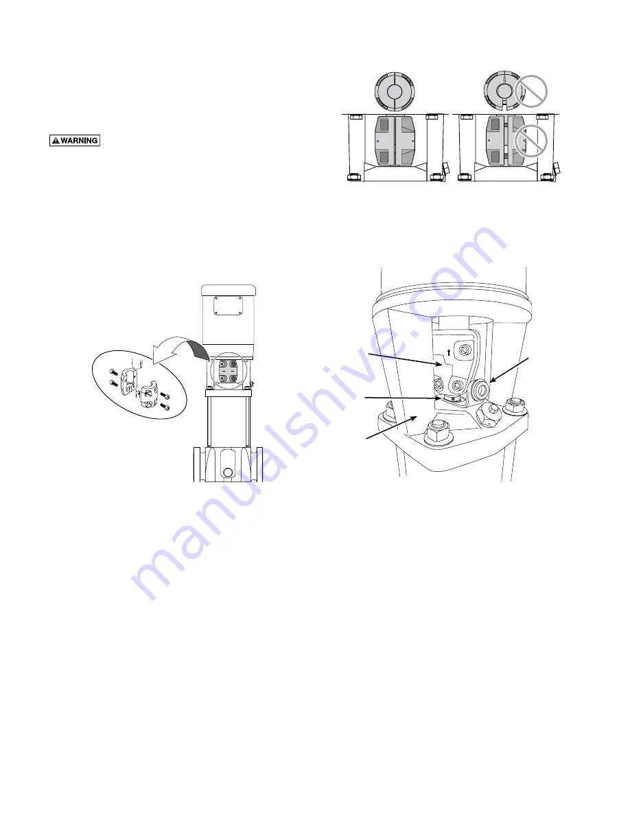
4.  Remove the socket head screws (3) and the coupling 

halves (2) from the shaft (16A). For additional 
reference, see Figure 10.


NOTICE: Socket head screws are metric. See 
Table VIII for specific metric driver sizes.

5.  Remove the shaft pin (5).
 

NOTICE: Pin has been discontinued and if present 
does not need to be reinstalled.

6.  Remove the capscrews (13), flatwashers (11), and 

lockwashers (12) that hold the motor (1) and the 
motor bracket (6) together.

7.  Pull the old motor up and off of the motor bracket. 

NOTICE: Note the location of the conduit box on 
the motor.

8.  Thoroughly clean the surfaces of the mounting 

flanges on the new motor and the pump end.

9.  Install the new motor on the pump with the conduit 

box in the desired position.

10. Lubricate the capscrews (13) with oil.
11. Reinstall the lockwashers, flatwashers, and capscrews 

that hold the motor and the motor bracket together, 
then tighten evenly and diagonally. See Table VIII for 
torque specifications.

12. Install the collar (13B) onto the shaft. With the collar 

resting on the motor bracket, tighten the collar bolt.

13. Raise the height of the pump shaft by inserting the 

stack height adjustment tool (see Figure 11B) below 
the collar.

14. Reinstall the coupling halves (2) on the pump and 

motor shaft.

15. Snug the socket head cap screws (3).
 

NOTICE: Torque settings are critical to prevent 
coupling movement. Refer to Table VIII for torque 
specifications.

16. Remove the stack height adjustment tool and secure 

it to the top of a staybolt.

17. Rotate the shaft to make sure that there is no 

interference. After assembly there should be a small 
gap between the collar and the bracket. If rubbing is 
noted, repeat steps 13, 14, and 15 to readjust pump 
shaft height.

18. Reinstall the coupling guards by snapping them 

into place.


NOTICE: The guards should be in place before the 
unit is run.

19. Open the suction and discharge valves. Turn the 

power back on.


Figure 11A - Make Sure that the Coupling Halves are 

Evenly Tightened


Figure 10 - Remove the Socket Head Screws and the 

Coupling Halves

Motor

Pump


Figure 11B - Using the stack height adjusting tool

Coupling

Collar

Stack Height 

Adjustment Tool

Bracket

Содержание BVM16-100

Страница 1: ...mation from the motor and pump nameplates for future reference Pump Model No Bill of Material No Motor Model No Motor Serial No H P Volts Hz Ph Rated Amp Draw In the U S BERKELEY 293 Wright St Delavan...

Страница 2: ...g is adequate to handle system pressure 5 Periodically perform maintenance inspection on pump and system components 6 Wear safety glasses at all times when working on pumps Inspect the Shipment The ve...

Страница 3: ...60 16 13 5 8 6 7 8 2 7 8 32 1 2 8 1 2 BVM4 80 7 18 1 8 13 5 8 6 7 8 2 7 8 34 5 8 8 1 2 BVM4 80 18 1 8 13 5 8 6 7 8 2 7 8 34 5 8 8 1 2 BVM4 90 19 5 32 15 1 4 8 3 3 8 37 13 16 10 5 8 BVM4 100 20 1 4 15...

Страница 4: ...18 1 2 13 5 8 6 7 8 2 7 8 35 8 1 2 BVMI X4 90 19 17 32 15 1 4 8 1 16 3 3 8 38 3 16 10 5 8 BVMI X4 100 20 5 8 15 1 4 8 3 3 8 39 1 4 10 5 8 BVMI X4 110 21 9 16 15 1 4 8 1 16 3 3 8 40 3 16 10 5 8 BVMI X4...

Страница 5: ...llow for minimum liquid flow through the pump Minimum liquid flow through the pump is needed for cooling and lubrication of the pump See Table IV Run the bypass relief valve and discharge pipe to a fl...

Страница 6: ...and all local codes and regulations Make sure that the motor voltage phase and frequency match the incoming electrical supply The proper operating voltage and other electrical information can be foun...

Страница 7: ...low the top of the pump NOTICE The suction pipe requires a check valve or isolation valve 1 Close the discharge isolation valve 2 Remove the vented priming plug 3 Pour liquid through the priming port...

Страница 8: ...of Head N PSHR Net Positive suction head required To be read from the NPSHR curve Figure 9 at the highest flow the pump will be delivering Hf Friction Loss in suction pipe in ft of head Hv Vapor pres...

Страница 9: ...tall the new motor on the pump with the conduit box in the desired position 10 Lubricate the capscrews 13 with oil 11 Reinstall the lockwashers flatwashers and capscrews that hold the motor and the mo...

Страница 10: ...ack without the stainless steel sleeve NOTICE Be sure to align either the small priming hole or the suction interconnector pin hole located on the bottom stage of the stack properly in the base of the...

Страница 11: ...l seat during disassembly and assembly 4 Clean the seal seat with a wet cloth 5 If replacing only the seal remove the rotating parts of the seal from the shaft by twisting and pulling up on them Disca...

Страница 12: ...vice again Regular Maintenance Checks The following checks should be made at regular intervals 1 The pump meets required performance and is operating smoothly and quietly 2 There are no leaks 3 The mo...

Страница 13: ...onally A Overload setting is too low B Low voltage at peak times 4 Motor starter has not tripped out but the motor does not run A Check 1 A B D and E 5 Pump capacity is not constant A Pump inlet press...

Страница 14: ...r with single phase power through a phase converter will void the warranty Note also that three phase motors must be protected by three leg ambient compensated extra quick trip overload relays of the...

Страница 15: ...16L 16A Shaft Ref Description 16D Top Diffuser 16E Spacer 16F Impeller 16G Diffuser 16H Spacer 16I Bearing 16J Shaft Washer 16K Nut 16L Suction Chamber 17 Sleeve O Ring Gasket on older models 18 Stain...

Страница 16: ...lat Washer 10 Vented Priming Plug 11 Flat Washer 12 Lock Washer 13A Capscrew 13B Collar 14 Conic Spring 15A Stationary Half of Mechanical Seal 15B Rotating Half of Mechanical Seal 16 Replacement Stack...

Страница 17: ...ckwasher 9 Staybolt Flat Washer 10 Vented Priming Plug 11 Flatwasher 12 Lockwasher 13A Capscrew 13B Collar 14 Spring Ring 15A Stationary Half of Mechanical Seal 15B Rotating Half of Mechanical Seal 16...

Страница 18: ...ybolt Lockwasher 9 Staybolt Flat Washer 10 Vented Priming Plug 11 Flat Washer 12 Lock Washer 13A Capscrew 13B Collar 14 Conic Spring 15A Stationary Half of Mechanical Seal 15B Rotating Half of Mechani...

Страница 19: ...19...

Страница 20: ......

Отзывы: