background image

5

Installation

 Risk of electric shock. Can shock, burn or 

kill. Ground pump motor correctly before connecting 
to power supply, per article 250-80 of the National 
Electrical Code (NEC) in the U.S., or the Canadian 
Electrical Code (CEC), as applicable.

Location

Locate pump in a dry, well ventilated area, not subject to 
freezing or extreme variations in temperature.
Mount pump a minimum of 6” from any obstruction 
or hot surface. Install the pump with the motor shaft 
vertical. Make sure that an adequate supply of cool air 
reaches the motor cooling fan. Maximum ambient air 
temperature is 104° F (40° C).
For open systems requiring suction lift, locate the pump 
as close to the water source as possible.

Foundation

Foundation should be concrete or a similarly rigid 
foundation to provide a secure, stable mounting base for 
the pump.
Secure pump to foundation using all bolt holes. Refer to 
Figures 2 and 3 for bolt plate dimensions. Be sure that all 
four pads on the base are properly supported.
Shim pump base to make sure that pump is level.

Piping

 Risk of explosion and scalding. Do not run 

pump with discharge valve closed; the water in the 
pump may boil, with risk of explosion and steam burns 
to anyone near.
If there is any danger of the pump running against a 
closed discharge valve, install a pressure relief or by-pass 
valve in the discharge pipe to allow for minimum liquid 
flow through the pump. Minimum liquid flow through 
the pump is needed for cooling and lubrication of the 
pump (See Table IV). Run the bypass/relief valve and 
discharge pipe to a floor drain or a tank for collection.

Suction pipe should be adequately sized (See Table V) 
and run as straight and as short as possible to keep 
friction losses to a minimum. Pipes, valves, and fittings 
must have a pressure rating equal to or greater than the 
maximum system pressure.

Pressure check the discharge piping as required by codes 
or local regulations.
“Inlet” and “Outlet” are marked on the pump base to 
show the direction of the liquid flow through the pump.
Install anti-vibration mountings on either side of the 
pump if a minimum noise level is desired.
Install isolation valves in both inlet and outlet pipes near 
the pump (see Figure 5). This allows for removal of pump 
for service without draining the system and isolation of 
the pump in case of a flooded suction condition.

TABLE IV – Minimum Pumping Rates

Type

 Liquid Temperature

+5° F to +250° F

BVM2

1 GPM

BVM4

2 GPM

BVM8

4 GPM

BVM16

8 GPM

TABLE V – Minimum Suction Pipe Sizes

Type

Pipe Size

BVM2

1-1/4” Nominal Diameter, Schedule 40 Pipe

BVM4

1-1/4” Nominal Diameter, Schedule 40 Pipe

BVM8

2” Nominal Diameter, Schedule 40 Pipe

BVM16 2” Nominal Diameter, Schedule 40 Pipe

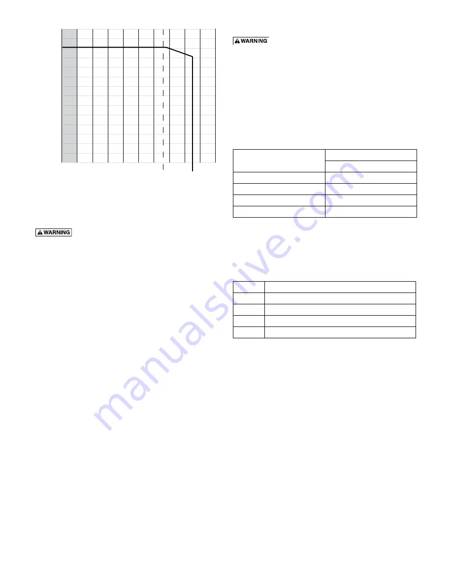
Figure 4 - Maximum Permissible Operating Pressure - all 

BVM models

0

30

60

90

120

150

180

210

240

270

300

330

360

390

420

212

0 to100 120 140 160 180 200 220 240

250

260 280

Pressure in PSI

Temperature in Degrees F

3   98

Содержание BVM16-100

Страница 1: ...mation from the motor and pump nameplates for future reference Pump Model No Bill of Material No Motor Model No Motor Serial No H P Volts Hz Ph Rated Amp Draw In the U S BERKELEY 293 Wright St Delavan...

Страница 2: ...g is adequate to handle system pressure 5 Periodically perform maintenance inspection on pump and system components 6 Wear safety glasses at all times when working on pumps Inspect the Shipment The ve...

Страница 3: ...60 16 13 5 8 6 7 8 2 7 8 32 1 2 8 1 2 BVM4 80 7 18 1 8 13 5 8 6 7 8 2 7 8 34 5 8 8 1 2 BVM4 80 18 1 8 13 5 8 6 7 8 2 7 8 34 5 8 8 1 2 BVM4 90 19 5 32 15 1 4 8 3 3 8 37 13 16 10 5 8 BVM4 100 20 1 4 15...

Страница 4: ...18 1 2 13 5 8 6 7 8 2 7 8 35 8 1 2 BVMI X4 90 19 17 32 15 1 4 8 1 16 3 3 8 38 3 16 10 5 8 BVMI X4 100 20 5 8 15 1 4 8 3 3 8 39 1 4 10 5 8 BVMI X4 110 21 9 16 15 1 4 8 1 16 3 3 8 40 3 16 10 5 8 BVMI X4...

Страница 5: ...llow for minimum liquid flow through the pump Minimum liquid flow through the pump is needed for cooling and lubrication of the pump See Table IV Run the bypass relief valve and discharge pipe to a fl...

Страница 6: ...and all local codes and regulations Make sure that the motor voltage phase and frequency match the incoming electrical supply The proper operating voltage and other electrical information can be foun...

Страница 7: ...low the top of the pump NOTICE The suction pipe requires a check valve or isolation valve 1 Close the discharge isolation valve 2 Remove the vented priming plug 3 Pour liquid through the priming port...

Страница 8: ...of Head N PSHR Net Positive suction head required To be read from the NPSHR curve Figure 9 at the highest flow the pump will be delivering Hf Friction Loss in suction pipe in ft of head Hv Vapor pres...

Страница 9: ...tall the new motor on the pump with the conduit box in the desired position 10 Lubricate the capscrews 13 with oil 11 Reinstall the lockwashers flatwashers and capscrews that hold the motor and the mo...

Страница 10: ...ack without the stainless steel sleeve NOTICE Be sure to align either the small priming hole or the suction interconnector pin hole located on the bottom stage of the stack properly in the base of the...

Страница 11: ...l seat during disassembly and assembly 4 Clean the seal seat with a wet cloth 5 If replacing only the seal remove the rotating parts of the seal from the shaft by twisting and pulling up on them Disca...

Страница 12: ...vice again Regular Maintenance Checks The following checks should be made at regular intervals 1 The pump meets required performance and is operating smoothly and quietly 2 There are no leaks 3 The mo...

Страница 13: ...onally A Overload setting is too low B Low voltage at peak times 4 Motor starter has not tripped out but the motor does not run A Check 1 A B D and E 5 Pump capacity is not constant A Pump inlet press...

Страница 14: ...r with single phase power through a phase converter will void the warranty Note also that three phase motors must be protected by three leg ambient compensated extra quick trip overload relays of the...

Страница 15: ...16L 16A Shaft Ref Description 16D Top Diffuser 16E Spacer 16F Impeller 16G Diffuser 16H Spacer 16I Bearing 16J Shaft Washer 16K Nut 16L Suction Chamber 17 Sleeve O Ring Gasket on older models 18 Stain...

Страница 16: ...lat Washer 10 Vented Priming Plug 11 Flat Washer 12 Lock Washer 13A Capscrew 13B Collar 14 Conic Spring 15A Stationary Half of Mechanical Seal 15B Rotating Half of Mechanical Seal 16 Replacement Stack...

Страница 17: ...ckwasher 9 Staybolt Flat Washer 10 Vented Priming Plug 11 Flatwasher 12 Lockwasher 13A Capscrew 13B Collar 14 Spring Ring 15A Stationary Half of Mechanical Seal 15B Rotating Half of Mechanical Seal 16...

Страница 18: ...ybolt Lockwasher 9 Staybolt Flat Washer 10 Vented Priming Plug 11 Flat Washer 12 Lock Washer 13A Capscrew 13B Collar 14 Conic Spring 15A Stationary Half of Mechanical Seal 15B Rotating Half of Mechani...

Страница 19: ...19...

Страница 20: ......

Отзывы: