background image

General BERGHOF 

Automation 

12 DC1000_HB_en_2D0982003ZD00.doc 

2VF100106FE00.doc 

1.5. 

Basic Safety Measures 

Working on the DC


Before beginning work on the DIALOG CONTROLLER you must always; 

• 

First ensure that the equipment is in a safe state; 

• 

Then first switch the DC off, followed by the equipment, and; 

• 

Only then disconnect the DC from the equipment. 


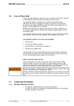
HAZARDOUS 
PROCESSES 


Hazards due to unforeseeable functional and processing movements when 
the INDUSTRIAL-PC is disconnected. 

These can result in death, serious injury or extensive property damage. 
All equipment components must be disconnected from the DIALOG 
CONTROLLER whenever the DIALOG CONTROLLER is not being used for op-
erational or control purposes, e.g., during maintenance or during functional 
checks after repairs. 

Lock out and tag out all equipment components after they have been 
switched off! 


Opening the DC 


First, please note all the tasks steps outlined in the above section “Working on the 
DC”. 
The supply voltage must be switched off before opening the housing or when com-
ponents are being installed or removed. 

To do this, switch the power supply to the DIALOG CONTROLLER off. Then re-
move the plug from the power supply socket on the DIALOG CONTROLLER.  


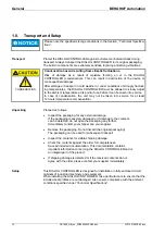
HAZARDOUS 

VOLTAGE 


Do not open the housing cover with the power switched on! 

Hazard due to contact with live components. 

This can result in death, serious injury or extensive property damage. 
Only open the housing cover once the DIALOG CONTROLLER has been safely 
disconnected from the power supply. 


Содержание DC1005

Страница 1: ...Z U N D E L H o l d i n g E n t e r p r i s e DIALOG CONTROLLER DC1005 DC1010 DC1012 V 1 3 Equipment Manual ...

Страница 2: ...y of the individual owner and are used by us strictly for the purposes of characterizing our product General Information on this Manual Content This manual describes the DIALOG CONTROLLER DC1005 and its modifications The product related information contained herein was up to date at the time of publication of this manual Completeness This manual is complete only in conjunction with the user manual...

Страница 3: ...mensions updated under Technical Specifications and in the graphs Plug unplug cycles added to the USB Pin Assignment section of the technical specifications Description Chemical Resistance for Touch Screens and I O Modules included Notice to SD card reader included Update under Power Supply Internal power pack Profibus master card and Profibus slave card ...

Страница 4: ...DIALOG CONTROLLER BERGHOF Automation 4 DC1000_HB_en_2D0982003ZD00 doc This page intentionally blank ...

Страница 5: ...agram 18 2 3 Technical Specifications DC1005 19 2 3 1 DC1005 Front View 21 2 3 2 DC1005 Rear View 21 2 3 3 DC1005 Dimensions 22 2 3 4 DC1005 Panel Cutout 23 2 4 Technical Specifications DC1010 24 2 4 1 DC1010 Front View 26 2 4 2 DC1010 Rear View 26 2 4 3 DC1010 Dimensions 27 2 4 4 DC1010 Panel Cutout 27 2 5 Technical Specifications DC1012 28 2 5 1 DC1012 Front View 30 2 5 2 DC1012 Rear View 30 2 5...

Страница 6: ...of Problems 50 4 CHEMICAL RESISTANCE 51 4 1 Resistance of the Touch Screen 51 4 2 Resistance of the Front Foil Sheeting to Chemicals 52 4 2 1 General Resistance of the Foil Sheeting Material 52 4 2 2 Resistance to Household Chemicals 53 4 2 3 Environmental Values 53 Lowest exposure temperature 53 Highest exposure temperature 53 Outdoor use 53 5 EXTENSION MODULES 55 5 1 I O Card With SC CAN Interfa...

Страница 7: ...nment 73 Pin overview 73 Power supply 73 Installation 73 PROFIBUS MASTER interface 74 5 3 PROFIBUS SLAVE Card 76 5 3 1 Technical Specifications 77 5 3 2 Front View and Pin Assignment 78 Pin overview 78 Power supply 78 Installation 78 PROFIBUS SLAVE interface 79 6 MAINTENANCE 81 6 1 Real Time Clock with Backup Battery 82 6 1 1 Battery Replacement 83 7 ANNEX 85 7 1 Environmental Protection 85 7 1 1 ...

Страница 8: ...DIALOG CONTROLLER BERGHOF Automation 8 DC1000_HB_en_2D0982003ZD00 doc This page intentionally blank ...

Страница 9: ...ALOG CONTROLLER The information contained in this manual is subject to change without prior notice 1 1 About This Manual This equipment manual is an integral part of the product Make sure the equipment manual is always available near the product s point of employment The manual contains information about the following topics Areas of application Safety Mechanical construction Electrical constructi...

Страница 10: ...sult in death serious injury or extensive property damage Potential danger Failure to observe the information indicated by this warning may result in death serious injury or extensive property damage Danger Failure to observe the information indicated by this warning may result in injury or property damage No hazard Information indicated in this manner provides additional notes concerning the prod...

Страница 11: ...always maintained in a complete and legible condition and is available at the point of employment of the DIALOG CONTROLLER That only properly qualified and authorized personnel mount install commission and maintain the DIALOG CONTROLLER That these specialists receive regular and ongoing instruction in all pertinent questions related to work safety and environmental protection and that they are fam...

Страница 12: ...ot being used for op erational or control purposes e g during maintenance or during functional checks after repairs Lock out and tag out all equipment components after they have been switched off Opening the DC First please note all the tasks steps outlined in the above section Working on the DC The supply voltage must be switched off before opening the housing or when com ponents are being instal...

Страница 13: ...hout arbitrary or unauthorized changes and exclusively by qualified users The regulations of the German professional and trade associations the German technical supervisory board TÜV the VDE Association of German electricians or other corresponding national bodies are to be observed Safety oriented fail safe systems Particular measures are required in connection with the use of SPC in safety orien...

Страница 14: ...ken into service for at least 12 hours temperature compensation Unpacking Proceed as follows Inspect the packaging for any external damage If the packaging is severely damaged or if damage to the contents can be detected do not open the packaging any further Immediately contact your shipper and your supplier Remove the packaging Do not discard the original packaging The packaging can be used for s...

Страница 15: ...color CSTN or TFT display are a vailable Above a diagonal screen size of 10 4 only TFT displays are employed Unit housing dimensions and protective method IP65 on the front do not depend on whether the version in question has a touch screen or matrix keypad Ethernet A 10 100 MBit s Ethernet interface is included TCP IP and UDP IP protocols offer highly flexible connections to visualization softwar...

Страница 16: ...from memory cards using the conventional MMC SD card interfaces If the SD card reader is activated then the second RS232 interface X5 is not longer available Performance feature overview Freescale POWERPCTM CPU 266 400 MHz Application program and data memory RAM 64 128 MB onboard 32 96 MB for the application Application program memory Flash 16 32 MB onboard 8 24 MB for the application Retain memor...

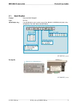
Страница 17: ...LOG CONTROLLER refer to the nameplate The code can be read as follows 2VF100227DG01_en cdr Nameplate 2VF100228DG01_en cdr D C 1 0 0 5 C T M P 6 6 1 2 3 4 5 6 7 8 9 10 11 12 13 14 15 16 05 10 12 15 10 4 12 1 5 0 1 5 7 M Color CSTN Color TFT C T Monochrome STN T K Touchpanel Keyboard MP266 MP400 Power PC 266 MHz Power PC 400 MHz Screen size diagonal Activation method Processor type Manufacturer s pr...

Страница 18: ... doc 2VF100107FE03 doc 2 2 DIALOG CONTROLLER DC1005 DC1010 DC1012 Construction 2 2 1 Block Circuit Diagram 2VF100233DG00_en cdr FRONT Front USB Inverter Display Touch Keyboard Display Unit X2 X1 X8 X7 X4 X5 X6 X3 24 V CPU Grafik CAN SIO Flash RAM USB X9 BASIS Controller ...

Страница 19: ...n Program memory and data memory RAM 64 MB onboard 32 MB for the application Retain memory 16 KB Real time clock Yes Development environment CP1131 CoDeSys 2 3 Dimensions and weight Dimensions WxHxD mm 194 x 172 x 52 6 mm front panel Weight approx 1 5 kg Operating conditions Ambient temperature range 0 C to 50 C Relative humidity max 85 non condensing monochrome max 75 Transport storage Ambient te...

Страница 20: ...hod RJ45 USB ports Number interface types 1 x host USB Rev 1 1 on rear 1 x host USB Rev 1 1 on front Plug unplug cycles max 1000 CAN bus ports Number interface types 2x standard CAN ISO 11898 Potential isolation CAN0 X6 potential isolated Transmission rate max 1 MBit s Terminating resistor Switchable Serial port Number interface types 2x RS232 1x RS485 Potential isolation RS485 X8 potential isolat...

Страница 21: ...oc DC1000_HB_en_2D0982003ZD00 doc 21 2 3 1 DC1005 Front View 2VF100229DG00 cdr 2 3 2 DC1005 Rear View 2VF100230DG00 cdr Geräte Anschlüsse Connections Abdeckung Erweiterungssteckplätze Cover Interface Boards Frontplatte Frontpanel Front USB Power Status LED ...

Страница 22: ...VF100234DG02 cdr max 52 ca 158 6 14 Freie Luftzirkulation free air circulation Freiraum clearance 20 mm max 52 ca 158 6 Freie Luftzirkulation free air circulation Freiraum clearance 20 mm Alle Maße in mm All dimensions in mm 194 172 DC1005M K R 6 F2 F3 F4 F5 F6 F1 Enter _ 5 7 DC1005C T DC1005T T Schraubenmontage Screwing assembly Bolzenmontage Bolt assembly Gewindebolzen M4 x 14 mm threaded bolt ...

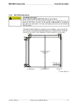
Страница 23: ... a base which is not level mechanical tension can result in cracks in the front panel The DIALOG CONTROLLER is intended for front installation A square panel cut out is required The support material thickness may not exceed 6 mm The panel cutouts are identical for units equipped with either a keyboard or a touchpad 2VF100235DG00 cdr Frontansicht Front view Fronttafel Ausschnitt 184 x 162 front pan...

Страница 24: ...memory 16 KB Real time clock Yes Development environment CP1131 CoDeSys 2 3 Dimensions and weights Dimensions WxHxD mm 360 x 260 x 77 6 mm front panel Weight approx 5 kg Operating conditions Ambient temperature range 0 C to 50 C Relative humidity max 90 non condensing Transport storage Ambient temperature range 20 C to 70 C Relative humidity max 90 non condensing Shock resistance Vibration Sinusoi...

Страница 25: ...d RJ45 USB ports Number interface types 1 x host USB Rev 1 1 on rear 1 x host USB Rev 1 1 on front Plug unplug cycles max 1000 CAN bus ports Number interface types 2x Standard CAN ISO 11898 Potential isolation CAN0 X6 potential isolated Transmission rate max 1 MBit s Terminating resistor Switchable Serial ports Number interface types 2x RS232 1x RS485 Potential isolation RS485 X8 potential isolate...

Страница 26: ...00_HB_en_2D0982003ZD00 doc 2VF100107FE03 doc 2 4 1 DC1010 Front View 2VF100241DG00 cdr 2 4 2 DC1010 Rear View 2VF100242DG00 cdr Geräte Anschlüsse Connections Abdeckung Erweiterungssteckplätze Cover Interface Boards Frontplatte Frontpanel Front USB ...

Страница 27: ...uare panel cut out is required The support material thickness may not exceed 6 mm The panel cutouts are identical for units equipped with either a keyboard or a touch panel 2VF100244DG00 cdr 0 30 270 330 340 Bohrungen 5 mm 6x drills Ø 0 4 66 232 236 170 310 Mittelachse Frontplatte centerline of front panel Mittelachse Ausschnitt centerline of front panel cut out Alle Maße in mm All dimensions in m...

Страница 28: ...memory 16 KB Real time clock Yes Development environment CP1131 CoDeSys 2 3 Dimensions and weights Dimensions WxHxD mm 360 x 260 x 77 6 mm front panel Weight approx 6 kg Operating conditions Ambient temperature range 0 C to 50 C Relative humidity max 90 non condensing Transport storage Ambient temperature range 20 C to 70 C Relative humidity max 90 non condensing Shock resistance Vibration Sinusoi...

Страница 29: ...d RJ45 USB ports Number interface types 1 x host USB Rev 1 1 on rear 2 x host USB Rev 1 1 on front Plug unplug cycles max 1000 CAN bus ports Number interface types 2x Standard CAN ISO 11898 Potential isolation CAN0 X6 potential isolated Transmission rate max 1 MBit s Terminating resistor Switchable Serial ports Number interface types 2x RS232 1x RS485 Potential isolation RS485 X8 potential isolate...

Страница 30: ...00_HB_en_2D0982003ZD00 doc 2VF100107FE03 doc 2 5 1 DC1012 Front View 2VF100272DG00 cdr 2 5 2 DC1012 Rear View 2VF100242DG00 cdr Geräte Anschlüsse Connections Abdeckung Erweiterungssteckplätze Cover Interface Boards Frontplatte Frontpanel Front USB ...

Страница 31: ...he DIALOG CONTROLLER is intended for front installation A square panel cut out is required The support material thickness may not exceed 6 mm The panel cutouts are identical for units equipped with either a keyboard or a touch panel 2VF100271DG00 cdr Alle Maße in mm All dimensions in mm Frontansicht Front view 4 0 136 272 276 4 0 26 206 346 386 412 416 Bohrungen 5 mm 8x drills Ø Fronttafel Ausschn...

Страница 32: ... 2 Connections Power supply Power for the DIALOG CONTROLLER comes from an external 24 VDC power supply Before continuing with the connection check that the external power supply meets the required specifications External power supply 24 VDC Output voltage 24 VDC SELV 15 20 Alternating component max 5 The direct voltage level may not fall below 20 4 V Power output Max 2 0 A at 24 VDC at 25 C Instal...

Страница 33: ...by means of an external short circuit and overload protector with a maximum of 12 A depending on the number of I Os X9 pin Assignment X9 1 External power supply 24 VDC 15 20 2 External power supply GND Phoenix MSTB 2 5 2 G 5 08 2 7 3 10 100 Base T Network Connection Ethernet The onboard 10 100 Base T Ethernet adapter with an RJ 45 connector is used to connect the unit to a network The LNK and RCV ...

Страница 34: ...ticks can be inserted and pulled during operation The inserted device is automatically detected and mounted in the media usbX directory When the USB stick is pulled the associated media usbX directory automati cally disappears provided no program is currently accessing it see above Either the first partition or if there are no partitions the entire memory will be mounted on the memory stick in oth...

Страница 35: ...is 50 kBit sec In addition the X6 interface CAN0 is equipped with a potential isolation X6 7 connector Pin assignment X6 7 1 NC Do not connect 2 CAN_L 3 CAN_GND 4 NC Do not connect 5 NC Do not connect Sub D9 M 6 NC Do not connect 7 CAN_H 8 NC Do not connect 9 NC Do not connect A terminating resistor can be switched using the S2 CAN0 and S3 CAN1 switches This is required if the associated CAN inter...

Страница 36: ...nance or a CoDeSys programming interface If the DIALOG CONTROLLER is started in the configuration mode the device can be configured in this mode using a serial PPP link Here too connection is via X4 X4 5 connector RS232 pin assignment X4 5 1 NC Do not connect 2 RXD 3 TXD 4 NC Do not connect 5 GND Sub D9 F 6 NC Do not connect 7 NC Do not connect 8 NC Do not connect 9 NC Do not connect If the SD car...

Страница 37: ... consumption level be exceeded the E bus and the connected modules may become nonfunctioning Therefore please note the current consumption of all E bus modules and all con nected consumers as a whole In some instances connection of consuming de vices e g an encoder can result in the current limit being exceeded Wherever possible you should only employ consumer devices with as low a cur rent requir...

Страница 38: ... push out insert and eject mechanism Gold plated contacts ensure low contact resistance and a service life of up to 10 000 plug in unplug cycles The write protection switch on the SD card is currently not recognized The SD card drive must be activated via the web con figuration In this case the application can no longer access the second serial port SIO2 X5 The files on the SD drive can be written...

Страница 39: ... associated equipment is switched on or when the power supply is connected Switching off The DIALOG CONTROLLER switches off when the associated equipment is swit ched off or the power supply is disconnected 3 2 Function Selection Indicators Diagnostics 3 2 1 Status Indicators The function of the status indicators frequently depends on the software develop ment environment employed on the DIALOG CO...

Страница 40: ... Basic recovery procedure in case of an ERROR STOP Determine the cause of the error indicated in the service menu on the display or can be read using a web browser Correct the cause of the error Perform a controller reset or alternatively Mode selection switch Service menu CoDeSys web browser Return the controller to operation CP1131 FORCE mode FORCE indicates that the application program is runni...

Страница 41: ...ion at the Ethernet interface and diagnostics functions in case of er rors to be simplified and accelerated Basic structure The service menu has a two part structure Parameter window The following four menu items are displayed here IP Config PLC Info Display Each menu item can contain additional subject related submenu items PLC window Up to two lines reflecting the current PLC status can be displ...

Страница 42: ...Cursor block The cursor block is used to navigate between the individ ual menu items on a given menu level Enter key The Enter key is used to confirm an input If a submenu permits values to be modified this modifica tion is performed with the Enter key The keys do not function in the service menu However using the cursor block you can navigate to a symbol displayed on the screen then use the Enter...

Страница 43: ...te the PLC Info to display the hardware and software version levels as well as diagnostic data Display to adjust contrast values IP Config service menu IP Config Check and adjust Ethernet parameters Ethernet IP ADDRESS Check and adjust the IP address IP address The keys can be used to adjust and set each individual IP address byte The Save IP button is then used to save the settings New settings w...

Страница 44: ...ill only take effect after a restart The EXIT button allows you to leave the menu without saving any changes which may have been made Ethernet GATEWAY IP Check and adjust the gateway IP address Gateway IP The keys can be used to adjust and set each individual gateway IP address byte The Save G IP button is then used to save the settings New settings will only take effect after a restart The EXIT b...

Страница 45: ...t setting The default settings should only be changed under special circumstances e g communi cations problems 100base Tx FD 100 MBit s full duplex 100base Tx HD 100 MBit s half duplex 10base T FD 10 MBit s full duplex 10base T HD 10 MBit s half duplex The Save button is used to save the new setting New settings will only take effect after a restart The EXIT button allows you to leave the menu wit...

Страница 46: ...cessfully carried out Info Status of the RESET PLC command PLC RUN PLC RUN PLC Command for the PLC program If there is a PLC program on the DIALOG CONTROLLER and if the program was suc cessfully started the service menu is closed and the PLC program is carried out If the PLC program is not cannot be carried out this may be due to one of the following causes There is no PLC program on the DIALOG CO...

Страница 47: ...ogger Displays all user activities as well as messages and software module prob lems To aid in diagnostics the entire content of the displayed page can be uploaded to a PC using the integrated Web Con figuration where it can then be saved and sent to BERGHOF The individual event logger messages as well as the web configuration are ex plained in the CANtrol PPC System In troduction manual ...

Страница 48: ...plied immediately and will remain in effect until the next restart even if you leave the menu with the EXIT but ton The Save button is used to save the new contrast setting The EXIT button allows you to leave the menu without saving any changes which may have been made although such changes will remain in effect until the next restart DIALOG CONTROLLERs with TFT displays The backlight brightness c...

Страница 49: ...nly loaded to RAM and was not saved as a boot project If the DIALOG CONTROLLER is switched off in this situ ation the system notes the ID number of the program previously loaded to RAM The displayed message now prevents the automatic startup of a possibly outdated PLC program Error correction Either load save and then start the new PLC program or use a reset command to start the saved and possibly...

Страница 50: ...ivation and possible problems the DIALOG CONTROLLER must be switched off when the front panel is cleaned Use a clean moistened lint free cloth to clean the front of the DIALOG CONTROLLER Please note the following to avoid damaging the front panel when cleaning it Never use high pressure or steam washers Never use caustic cleaning agents even diluted abrasives or hard objects to clean the panel Do ...

Страница 51: ...ing chemicals if ex posed to them for a period of one hour at a temperature of 21 C Industrial chemicals Household chemicals Acetone Dichloromethane Methyl ethyl ketone Isopropyl alcohol Hexane Turpentine Naphtha Lead free gasoline Diesel oil Motor oil Transmission fluid Antifreeze Ammonia based glass cleaners Laundry detergent Cleansers Fantastic Formula 409 Joy etc Vinegar Coffee Tea Grease Cook...

Страница 52: ...her N butyl acetate Amyl acetate Butyl cellosolve Ether Acetone Methyl ethyl ketone Dioxan Cyclohexanon MIBK Isophoron Formic acid 50 Acetic acid 50 Phosphoric acid 30 Hydrochloric acid 36 Nitric acid 10 Trichloro acetic acid 50 Sulfuric acid 10 Ammonia 40 Caustic soda 40 Potassium hydroxide 30 Alkali carbonate Bichromate Potassium ferrocya nide Acetonitril Sodium bisulfate Drilling emulsions Dies...

Страница 53: ...ey Ajax Vim Domestos Vortex Windex Very close examinations would reveal mild discoloration after exposure to the following materials Mustard Tomato juice Ketchup Lemon juice 4 2 3 Environmental Values Lowest exposure temperature After 0 5 million activations at 40 C AUTOTEX exhibited no functional impair ment Highest exposure temperature High humidity 80 rel H 40 C Moderate humidity 10 80 rel H 60...

Страница 54: ...Chemical Resistance BERGHOF Automation 54 DC1000_HB_en_2D0982003ZD00 doc 2VF100123FE00 doc This page intentionally blank ...

Страница 55: ...ZD00 doc 55 5 Extension Modules 2VF100304DG00 cdr Extension modules Slot Type Designation A1 A2 A3 I O card with SC CAN U DC XS 12 8 4 CSC X PROFIBUS master ABM DPV HMS X PROFIBUS slave ABS PDP HMS X Steckplatzbezeichnung für Erweiterungsmodule Slot marking for extension modules ...

Страница 56: ...or 0 20mA 1 CAN interface for contact line systems with monitoring capability Connection for a 5 place 7 segment display with remote control receiver Standard delivery The standard control module delivery comprises I O card installed in the DIALOG CONTROLLER IN 1 8 SC CAN 1 M1 I O 13 16 9 7Seg IR SC Test IN 9 12 2 3 1 2 X10 X13 X9 X1 X6 X4 X1 X2 X5 X7 OUT 1 8 X3 X8 X11 M1 M1 M1 L1 1 2 3 1 2 3 1 2 ...

Страница 57: ...upply voltage pole reversal Yes Potential isolation No Digital inputs outputs DIO Number of inputs 12 X1 X2 of which 4 can be used as 24V encoder inputs counter frequency at 4x evaluation 20 kHz Number of outputs 8 X9 Number of inputs outputs 4 X2 Output current 0 5 A Short circuit protection Yes Potential isolation Yes Connection technique Standing front wiring for 3 81 terminal strips not part o...

Страница 58: ...e equipped with an external short circuit and overload protection with an activation current of 8 A max depend ing on the number of I Os External power supply The CAN communications interface is supplied from the DIALOG CONTROLLER power supply IN 1 8 SC CAN 1 M1 I O 13 16 9 7Seg IR SC Test IN 9 12 2 3 1 2 X10 X13 X9 X1 X6 X4 X1 X2 X5 X7 OUT 1 8 X3 X8 X11 M1 M1 M1 L1 1 2 3 1 2 3 1 2 3 4 5 6 7 8 1 2...

Страница 59: ...ension Modules 2VF100124FE01 doc DC1000_HB_en_2D0982003ZD00 doc 59 Installation The I O card is factory installed and may only be installed in the DIALOG CONTROLLER in the position shown in the figure below 2VF100306DG00 cdr ...

Страница 60: ...ine connection using two separate conductors Any other type of circuit construction e g a bridge between the two PE connec tions may result in functional errors or functional inefficiency of the SC_CAN Termination The SC_CAN must be terminated at both line ends The values for these terminating resistors deviate from the ISO 11898 CAN Bus standard and they can be ordered separately from BERGHOF CTR...

Страница 61: ...is a point to point interface It is only for devices with an ISO11898 CAN interface CAN telegrams cannot be sent No terminating resistors may be employed Pin assignment for an adapter cable 2 pin post 2 54 9 pin Sub D Pin Signal Signal Pin 1 CAN CAN HIGH 2 2 GND CAN LOW 7 External 7 segment display For special applications an external 7 segment display with integrated infrared re ceiver can be con...

Страница 62: ... Voltage measurement Nominal input voltage value 0 10 V Maximum input voltage value 12 V General data Input filter 1st order τ 1ms for current τ 10ms for voltage measurement Conversion method Successive approximation no error codes Resolution 10 bit 1 LSB 78 1 µA 39 06 mV Accuracy within the 0 50 C tempera ture range 2 LSB 1 Pole reversal protection Yes Sampling rate approx 1 ms Due to internal pr...

Страница 63: ...ult in the destruction of the module and or the sensors With the group power supply switched off the connected sensors may produce feedback via the output transistors Make sure that the sensors are all supplied from the same power source as the module s associated I O group 2VF100307DG00 cdr 1 2 3 4 5 6 7 8 9 1 2 3 4 5 6 7 8 9 1 2 3 4 5 6 7 8 9 1 2 3 4 5 6 7 8 9 1 2 3 4 5 6 7 8 9 1 2 3 4 5 6 7 8 9...

Страница 64: ...rference suppression Inputs are read in cycles Impulses of 100 µs are suppressed by the hardware The shortest possible sampling rate is 250 µs In order for impulses to be properly detected they must be longer than the sam pling rate defined by the software Multiple sampling can be programmed to suppress interference impulses The sampling rate and multiple sampling filtering can be activated in ind...

Страница 65: ...cting a conductor Other than this there are no relevant re strictions Comply with all locally applicable re quirements as well as those in ac cordance with EN 61131 3 Where the risk of lightning exists please consult the manufacturer Nominal load voltage L Pole reversal protection DC 24 V SELV Yes Potential isolation Yes optocoupler in groups Status indicator None Alarms Definable depending on the...

Страница 66: ...Extension Modules BERGHOF Automation 66 DC1000_HB_en_2D0982003ZD00 doc 2VF100124FE01 doc Digital input operating ranges 2VF100010DG00 cdr ...

Страница 67: ...switch to 0 LOW Protected output All outputs are protected by an internal current limiter and thermal overload protec tion In case of an overload the current limiter switches the overloaded output off Once the overload has been corrected and the unit has cooled down the output can be reactivated via the program A quick deactivation using a terminal voltage of 50 V referenced to L protects all outp...

Страница 68: ...ut puts Short circuit protection 1 Activation threshold Yes electronic current limiter min 0 5 A typically 0 9 A 1 Current is electronically limited Activation of the short circuit protection results in a thermal overload which activates the thermal overload protection Output delay From 0 to 1 From 1 to 0 max 0 5 ms max 0 5 ms Output capacitance 20 nF Reference voltage Voltage drop at reference cu...

Страница 69: ...rload behavior 2VF100021DG00 cdr No assurance as to whether a shutdown or a return to the working range will oc cur can be made within the current limiter scatter band Therefore this state should be avoided The output will again be operational once the overload has been corrected and the unit has cooled down ...

Страница 70: ...l IN 24V 6 IN6 Digital IN 24V 7 IN7 Digital IN 24V X1 8 IN8 Digital IN 24V 1 IN9 Digital IN 24V 2 IN10 Digital IN 24V 3 IN11 Digital IN 24V 4 IN12 Digital IN 24V 5 I O13 Digital I O 24V 6 I O14 Digital I O 24V 7 I O15 Digital I O 24V X2 8 I O16 Digital I O 24V 1 OUT1 Digital OUT 24V 2 OUT2 Digital OUT 24V 3 OUT3 Digital OUT 24V 4 OUT4 Digital OUT 24V 5 OUT5 Digital OUT 24V 6 OUT6 Digital OUT 24V 7...

Страница 71: ...w PROFIBUS DP master bus module Max of 125 slave nodes can be connected Max 3 KB process data 1536 byte input and 1536 byte output data Baud rates 9600 bit sec 12 MB sec Potential isolated PROFIBUS MASTER RS485 interface with integrated DC DC converter and optocouplers Cyclic DP master services Standard delivery The standard delivery comprises PROFIBUS MASTER card installed in the DIALOG CONTROLLE...

Страница 72: ...nterference emission EN 61000 6 4 Industrial application Interference resistance EN 61000 6 2 Industrial application Protection class III Insulation resistance EN 61131 2 DC 500 V test voltage Protection type IP 20 Supply voltage current consumption Module electronics power supply connection voltage 5 V max 370 mA from the DIALOG CONTROLLER s mains power supply PROFIBUS MASTER interfaces Number an...

Страница 73: ...xternal power supply The PROFIBUS MASTER communications interface is supplied from the DIALOG CONTROLLER s power supply Installation The PROFIBUS MASTER card is factory installed and may only be installed in the DIALOG CONTROLLER in the position shown in the figure below 2VF100309DG00 cdr Indicators X1 Diag X2 Profibus DC Profibus DP M Database Comm Master Token 2 1 3 4 ...

Страница 74: ...12 MB sec can be set All cyclic PROFIBUS DP services are available PROFIBUS X2 jack Pin assignment of the galvanically isolated field bus interface Pin Signal Description 1 N C Do not connect 2 N C Do not connect 3 B RS485 signal 4 RTS Ready to send 5 GND Bus ground 6 5V Bus output 7 N C Do not connect 8 A RS485 signal 9 N C Do not connect Diag X1 pins Pin assignment serial diagnostics interface P...

Страница 75: ...eSys controller configu ration with a GSD file As of Version 1 0 this GSD file will be part of the BERGHOF target installation package Indicator LEDs Indicator Signal Description Green Operating mode Green flashing Delete mode Red Stop mode 1 Master Off Offline Green Databank OK Green flashing Database load procedure running Red Database invalid 2 Database Off No database available Green Data exch...

Страница 76: ... input and 244 byte output data all together 416 byte Automatic baud rate recognition 9600 bit sec 12 MB sec Potential isolated PROFIBUS SLAVE RS 485 interface with integrated DC DC converter and optocouplers All required DP services as well as user parameter data and device specific diagnostics Standard delivery The standard delivery comprises PROFIBUS SLAVE card installed in the DIALOG CONTROLLE...

Страница 77: ...000 6 4 Industrial application Interference resistance EN 61000 6 2 Industrial application Protection class III Insulation resistance EN 61131 2 DC 500 V test voltage Protection type IP 20 Supply voltage current consumption Module electronics power supply connection voltage 5 V max 350 mA from the DIALOG CONTROLLER s mains power supply PROFIBUS SLAVE interfaces Number and type of interfaces 1 PROF...

Страница 78: ...y The PROFIBUS SLAVE communications interface is supplied from the DIALOG CONTROLLER s power supply Installation The PROFIBUS SLAVE card is factory installed and may only be installed in the DIALOG CONTROLLER in the position shown in the figure below 2VF100311DG00 cdr Indicators S1 S3 S2 Address x1 Termination ON OFF Address x10 X1 Profibus DC Profibus DPS Online Offline n c Error 1 2 3 4 ...

Страница 79: ...B sec The PROFIBUS station address is set with the CoDeSys controller configuration Rotary switches S1 and S2 have no effect and can therefore not be used in an application specific manner PROFIBUS X1 jack Pin assignment of the galvanically isolated field bus interface Pin Signal Description 1 N C Do not connect 2 N C Do not connect 3 B RS485 signal 4 RTS Ready to send 5 GND Bus ground 6 5 V Bus o...

Страница 80: ...C Not used Green Online data exchange permitted 2 Online Off Not online Red Offline no data exchange possible 3 Offline Off Not offline Red flashing at 1Hz Configuration error initialized data length does not match configuration Red flashing at 2Hz Missing user parameter initialized data length does not match configuration Red flashing at 4Hz Initialization error in the ASIC 4 Error Off No diagnos...

Страница 81: ...ult in death serious injury or extensive property damage Only open the housing cover once the DIALOG CONTROLLER has been safely disconnected from the power supply Maintenance work to the DIALOG CONTROLLER can result in damage If metal objects such as screws nuts tools or other conducting objects fall on the PCB If connecting cables are loosened removed or incorrectly reconnected After maintenance ...

Страница 82: ...ect the real time clock s function Overvoltage Check the battery type and device hardware Undervoltage Replace the battery The following battery charge levels are important 3 2 Volt Typical value for a new battery This value may not be exceeded 3 0 Volt Nominal battery voltage 2 5 Volt The battery should be replaced 2 0 Volt The battery must be replaced immediately in order to ensure the proper fu...

Страница 83: ...ing charge current is 2 5 mA or more The use of any other battery may result in fire or explosion The real time clock s backup battery can be replaced without the risk of data loss provided the DIALOG CONTROLLER supply voltage is switched on Battery replacement The battery is held in place by a spring clip Never lift the spring clip retainer as this can destroy the clip Push the old battery out to...

Страница 84: ...Maintenance BERGHOF Automation 84 DC1000_HB_en_2D0982003ZD00 doc 2VF100109FE01 doc This page intentionally blank ...

Страница 85: ...k of destruction or malfunction Disconnect all incoming power supplies before working on our modules this also applies to connected peripheral equipment such as externally powered sensors programming devices etc All ventilation openings must always be kept free of any obstruction The modules are maintenance free when used correctly Clean only with a dry non fluffing cloth Do not use detergents 7 3...

Страница 86: ...Annex BERGHOF Automation 86 DC1000_HB_en_2D0982003ZD00 doc 2VF100055FE02 doc 7 4 Nameplate 2VF100080DG01 cdr ...

Страница 87: ... level of the module as supplied ex works 6 Supply voltage 7 Date internal code 8 CE mark The Version supply version panel specifies the design level of the mod ule as supplied ex works When replacing a module users with the CNW CANtrol Node Wizard tool can read off the current software version of the newly supplied module and then re load their own software version for a particular project if nec...

Страница 88: ... 2 EN61131 2 Programmable controllers Part 2 Equipment requirements and tests IEC61131 3 EN61131 3 Programmable controllers Part 3 Programming languages IEC61131 4 EN61131Bl1 Programmable logic controllers Supplementary Sheet 1 User guidelines IEC61000 6 4 EN61000 6 4 German EMC Act Emitted interference IEC61000 6 2 EN61000 6 2 German EMC Act Noise immunity ISO DIS 11898 Draft International Standa...

Отзывы: