21.12.98
Operating manual
04_GB
ACP 3000 — 0.37–15.0
53
Berges electronic
•
D–51709 Marienheide-Rodt
•
Tel. 02264/17-0
•
Fax 02264/17126
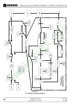
The PI Controller operates within the limits set by parameter
A1-FCORR
, the value of which
establishes the frequency band across which the value of the integrator and the output of
the PI Controller may vary. If Feed-Forward is active, the output of the PI Controller is the
reference frequency
12-FOUT
±
A1-FCORR
, and the integrator's value is ±
A1-FCORR
.
Note that the final output of the PI Controller cannot be less than 0.00 Hz nor greater than
400.00 Hz.
The output of the PI Controller is sent to the ASIC after the proper frequency conversion.
The controller works in one direction of rotation which must be set by FWD and REV com-
mands. A change in direction while the controller is active yields unpredictable results.
The PI controller is limited in its application by the minimum resolution available through the
feedback terminal. Since the feedback terminal voltage is scaled through an 8-bit analog-
to-digital converter, the reaction of the PI loop is reduced.
For example, if the inverter is set to run from 0.00 to 60.00 Hz and the feedback is coming
from a tachometer rated at 50 V/1000 rpm and conditioned to be between 0–10 V with 2000
RPM being full scale, then the minimum change that the 8-bit A/D converter can register is
8 rpm. This means that, worst case, the speed can drop by 8 rpm when a load is applied,
but typical accuracy is ±2%.
Input CTS or a STOP command (or inputs FWD and REV active at the same time) stops
the inverter and resets the integrator part (sIPart) of the PI Controller when the value of
12-
FOUT
falls below 0.10 Hz.
6.3
Reference and Feedback Inputs
A.
Configuration of Inputs
The PI reference value is input from either the keypad or the VIN2 terminal. The PI feedback
value is input from the VIN1 terminal. An error signal is calculated by the microprocessor
which adjusts the speed of the inverter within a range limited by the
A1-FCORR
parameter.
The PI feedback input (VIN1) is selectable through J20 as 0 to5 VDC, 0-10 VDC, 0 to 20
mA, or 4 to 20 mA. The PI reference input (VIN2) is selectable through J20 as 0 to 5 VDC
or 0 to 10 VDC.
Parameter
24-FSEL
is used to set the feedback input to be direct, inverted, or a 20% offset
from the minimum. This parameter must also be set to 16, 17, 18, or 19 to use VIN2 as the
reference input. Enabling the PI Controller without properly setting
24-FSEL
could result in
the use of a combination of VIN1 and VIN2 as the reference signal which will give unpre-
dictable results.
B.
Scaling the Feedback Input
The feedback input (VIN1) is scaled between 0.00 Hz and 1.125 times FMAX. For example,
if VIN1 is set to “direct” and FMAX is 60.00 Hz, then a full scale feedback signal will corre-
spond to 67.50 Hz.
This feedback input can also be scaled, via
B5-KIN
, from 0 to 255 which corresponds to a
range of 0 to 1.99. For example, if B5-KIN = 64, then a full scale feedback signal would cor-
respond to 33.75 Hz.
The function of scaling is to compensate the input for conditioning difficulties of the feed-
back signal. For instance, if the feedback is from an analog tachometer that gives a 50 V /
1000 rpm signal and the inverter is set up to have an FMAX of 60.0 Hz (which means that
VIN1 needs to read a signal of 67.5 Hz), then the maximum voltage from the tachometer
will be 101.25 V.
StockCheck.com
Содержание ACP micro 3000
Страница 1: ...Operating manual 0 37 15 kW S t o c k C h e c k c o m ...
Страница 2: ...S t o c k C h e c k c o m ...
Страница 75: ...S t o c k C h e c k c o m ...

