


ENGLISH
14
MySMART
15
MySMART C.S.I.
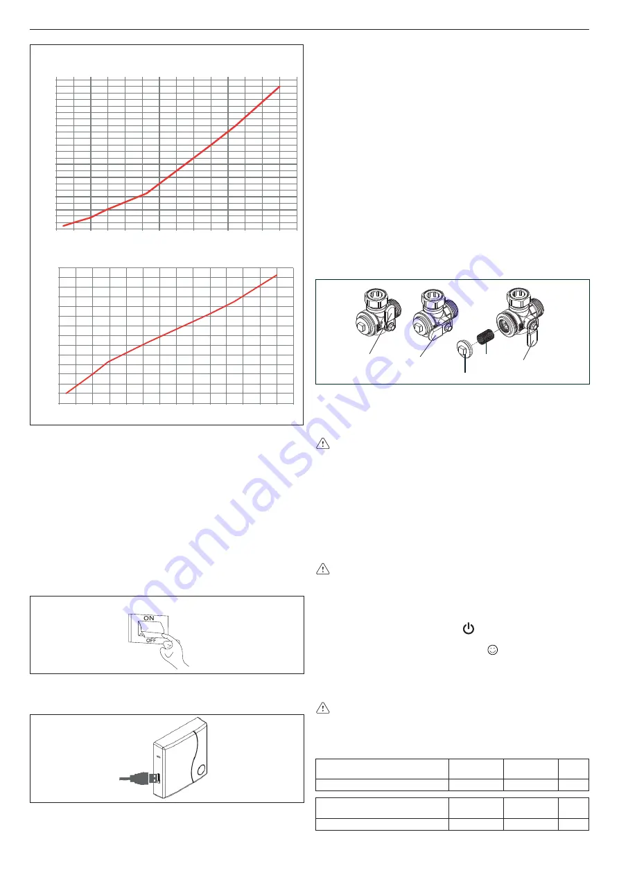
CO s.a. curve (Qnheating)
0
10
20
30
40
50
60
70
80
90
100
110
120
130
140
150
160
170
180
190
200
210
220
230
240
2
4
6
8
10
12
14
16
18
20
22
24
26
28
30
HTG curve (Qnheating)
Fan rotations (rpm)
Heat output (kW)
CO emissions s.a. (p.p.m.)
Heat output (kW)
800
1200
1600
2000
2400
2800
3200
3600
4000
4400
4800
5200
5600
6000
6400
2
4
6
8
10
12
14
16
18
20
22
24
26
28
30
5 - MAINTENANCE
To ensure product characteristics and efficiency remain intact and
to comply with prescriptions of current regulations, it is necessary to
render the appliance to systematic checks at regular intervals.
When carrying out maintenance work, observe the instructions given
in chapter 1 “Warnings and safety”.
Turn off the appliance before carrying out work or maintenance of
structures near the flue discharge connections and/or fume dis-
charge devices and their accessories. Once work is completed, a
qualified technician must check the efficiency of the appliance.
IMPORTANT:
before undertaking any maintenance or cleaning op-
erations, use the switch of the appliance itself and the system to in-
terrupt the electrical supply and close the gas supply using the tap
on the boiler.
It is also OBLIGATORY
to disconnect the cable connecting the WiFi
Box and the boiler
- return power to the boiler
- interrupt the vent cycle as described in the section “4.2 Appliance
ignition” on page 10.
5.1 Routine maintenance
This normally means the following tasks:
- removing any oxidation from the burner;
- removing any scale from the heat exchangers fume side;
- checking and cleaning the drainage pipes;
- checking the external appearance of the boiler;
- checking the ignition, switch-off and operation of the appliance, in
both domestic water mode and heating mode;
- checking the seal on the gas and water couplings and pipes;
- checking the gas consumption at maximum and minimum output;
- checking the position of the ignition-flame detection glowplug;
- check the “no gas” safety system;
- check operation of the check valve if it is installed (see section 3.12
“Installation on collective flues in positive pressure”).
- cleaning the filter inside the heating return line tap. Follow the in-
structions below:
- set the lever to “filter cleaning“
- unscrew plug
A
- remove the filter
B
and clean it
- remove any dirt in the filter chamber
- put back the filter
- put back the plug
A
- set the lever to the opening position
opening
position
closing
position
filter cleaning
position
A
B
-
Do not clean
the appliance or its parts with easily inflammable
substances (e.g. benzine, alcohol, etc.).
- Do not clean panels, painted parts and plastic parts with paint
thinner. Panel cleaning must be carried out only with soapy water.
After routine and extraordinary maintenance operations have
been carried out, fill the siphon, following the instructions in the
section “Preliminary cheks”.
5.2
Extraordinary maintenance
These tasks restore appliance operation in accordance with the
design and regulations - e.g. following the repair of an accidental
fault.
This normally means:
- replacement
- repair
- overhaul of components.
These tasks require special means, equipment and tools.
During the initial installation phase, or in the event of extraordinary
maintenance, you are advised to activate the procedure to
discharge air from the heating circuit and boiler (see section 3.4).
5.3
Checking the combustion parameters
MySMART C.S.I.:
- Position the function selector on to switch off the boiler (fig.
48)
- Turn the DHW temperature selector on (fig. 48).
Wait until the ignition of the burner (about 6 seconds). The display
shows “ACO”, the boiler operates at full power heating.
- Remove the screw
C
and the cover
E
on the air box (fig. 49).
- Insert the probes of the analyzer in the positions provided on the
air box.
Th
e flue gas analysis probe must be fully inserted as far
as possible.
- Check that the CO
2
values match those given in the table, if the
value shown is different, change it as indicated in the chapter
entitled “Gas valve calibration”.
MAXIMUM CO
2
METHANE
GAS (G20)
LIQUID GAS
(G31)
28 C.S.I.
9,0
10,0
%
MINIMUM CO
2
METHANE
GAS (G20)
LIQUID GAS
(G31)
28 C.S.I.
9,0
10,0
%
Содержание 20109808
Страница 103: ......


