11
EN / CZone® Contact 6 PLUS User & Installation Manual
NETWORK CONFIGURATION
CZone modules communicate with each other over a NMEA2000 CAN BUS network. Each module needs a unique
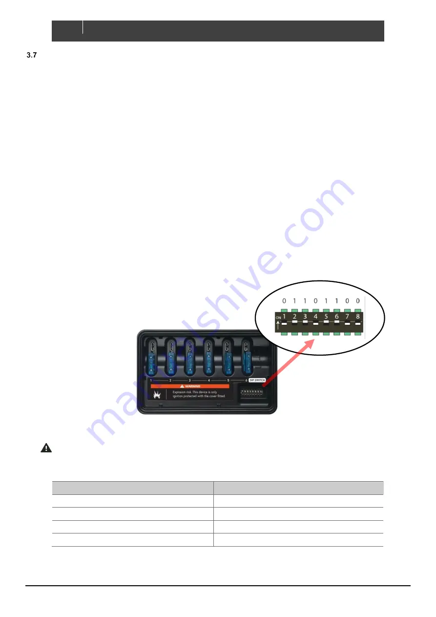
address, this is achieved by carefully setting the dipswitch on each module with a small screwdriver. The dipswitch on
each module must match the setting in the CZone configuration.
The Contact 6 PLUS comes pre-loaded with a factory configuration to provide plug-and-play functionality when installed
with a CZone Waterproof Keypad. The factory configuration provides basic switching functionality with one-to-one switch
input to channel output mapping.
Standalone Installation
•
Set the dipswitch on the Contact 6 PLUS and Waterproof Keypad to match the below table.
•
Connect the Contact 6 PLUS to the Waterproof Keypad with the CZone Smart Harness or NMEA2000 network.
•
Change any desired circuits to have momentary functionality instead of latching (see Initial Power up section).
Networked Installation
•
To install the Contact 6 PLUS with other networked CZone modules, or to achieve advanced functionality such
as timers, load shedding or one touch Modes of operation, a custom configuration needs to be installed.
•
Set the dipswitch on the Contact 6 PLUS to match the configuration file.
•
All other CZone modules must have the dipswitch set to same as the configuration file.
The example below shows a dipswitch setting of 01101100 where 0 = OFF and 1 = ON
Setting Dipswitch
IMPORTANT -
Each CZone device must have a unique dipswitch number and the dipswitch of the device
must match the dipswitch set in the configuration file.
1.
Factory configuration table
Module
Dipswitch
Contact 6 PLUS
10000000
Portrait Waterproof Keypad
00000001
Landscape Waterproof Keypad
00000011
Display Interface
11101000
NOTE -
If you have a compatible MFD or Display Interface, the factory configuration will work and populate
circuits 1 - 6 on the display for basic on/off control.


