


6
INSTRUCTION MANUAL
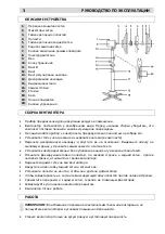
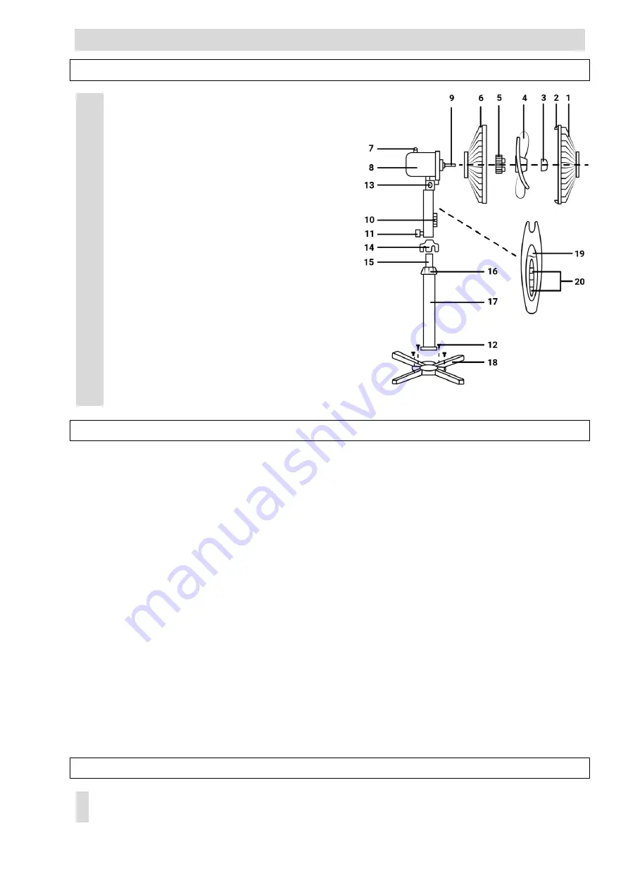
DESCRIPTION
1.
2.
3.
4.
5.
6.
7.
8.
9.
10.
11.
12.
13.
14.
15.
16.
17.
18.
19.
20.
Front grille
Grille clips
Blade cap
Blades
Rear grille nut
Rear grille
Oscillating knob
Motor
Motor shaft
Control box
Screw B
Screw
Vertical adjustment screw
Stand cover
Extension pole
Out-joint
Stand tube
Stand base
Night light
Switch mode buttons
ASSEMBLING INSTRUCTIONS
The device is intended for air circulation in the room.
Fan is packed disassembled. Before assembling make sure that all the required parts are
undamaged and included into the set.
Do not plug in the device before its assembling is finished.
Tighten stand tube to stand base with screw. Fix base cover to stand base with a screw
(supplied with a set).
Unscrew out-joint, put the stand cover and base cover on the stand base, pull the extension
pole out then tighten the out-joint again.
Place control box firmly on top of extension pole, tighten screw B.
Unscrew the blade cap by turning clockwise and rear grill nut by turning counter clockwise and
put both blade cap and rear grill nut off the motor shaft.
Put rear grille on motor shaft.
Secure it with rear grille nut.
Slide blades on motor shaft so that claws on motor shaft match the blades slots.
Screw blade cap on shaft by turning counter clockwise.
Put front grille on rear grille and close clips or screw grille ring to secure grilles together.
Adjust the fan vertically by vertical adjustment screw.
The fan is ready for work.
OPERATION MANUAl
CAUTION: To avoid electroconvulsive shock or fire danger, do not operate fan under the
conditions of increased humidity.
Place fan only onto dry flat unyielding surface.


