

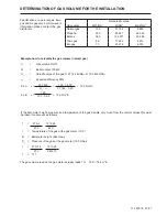


172 425 16 08-01
ELECTRIC EQUIPMENT
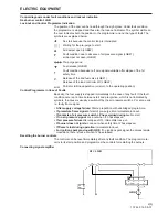
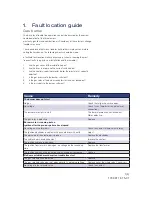
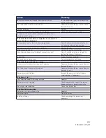
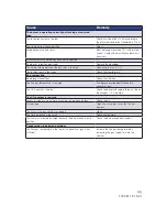
Control diagnosis under fault conditions and lockout indication
Gas burner control: LGB
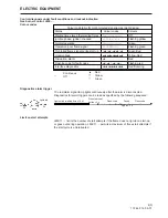
Lock-out and Control Programme Indication
The position of the cam can be read through the sight-glass. Under fault condition
the programme is stopped and thus also the lock-out indicator. The symbol visible on
the cam indicates both the position in the programme run and the type of fault. The
symbols are explained below:
No start because the control loop is interrupted
Waiting for the pre-purge to start
Air damper open (LGB22)
Fault condition due to absence of air pressure signal (LGB21),
air damper not open (LGB22)
Pre-purge period
Fuel release (LGB22)
Fault condition because no flame signal available after elapse of the 1st
safety time
Release of the 2nd fuel valve (LGB21)
Release of the load controller LR (LGB22)
Partial or full load operation (or return to the operating position)
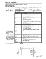
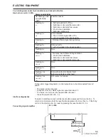
Control Programme in Case of Faults
Basically, the fuel supply is stopped immediately in the case of any fault. If the fault
condition occurs at a time between start and pre-ignition, which is not indicated by
symbols, the cause is usually a switch-off by the air pressure switch LP or a too early,
i.e. faulty, flame signal.
• After supply voltage failure:
Start-up repetition with unabridged programme.
•
If premature flame signal
at start of pre-purge time: Immediate lock-out.
• If contacts of air pressure switch LP have welded during tw:
No start.
• If no air pressure signal:
Lock-out when t10 has elapsed.
• If air pressure failure
after elapse of t10: Immediate lock-out.
• If burner does not ignite:
Lock-out when safety time t2 has elapsed.
•
If flame is lost during operation:
Immediate lock-out.
• For ignition spark proving with QRE
: If no ignition spark signal, the valves remain
closed and there is lock-out when t2 has elapsed.
Resetting the burner controls
The controls can be reset immediately after any fault condition. The programme re-
verts to its start position and programmes the controls for restarting the burners.
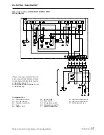
Connecting signal amplifier
2(5)
A1 = LGB
GP
R/W
L
N
br
bl
rt
sw
sw
rt
Q1 = AGQ 1...
QRA
1
11
12
2
Содержание STG 146
Страница 2: ......
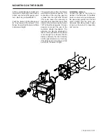
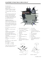
Страница 18: ...172 305 50 07 01 GENERAL INSTRUCTIONS Control of burner head Air adjustment Adjustment of inner assembly...
Страница 27: ......
Страница 28: ...Enertech AB P O Box 309 SE 341 26 Ljungby www bentone se www bentone com...