13
Bentone
165 205 44
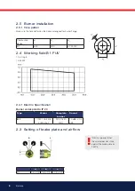
3.6 Burner installation
3.6.1 Hole pattern
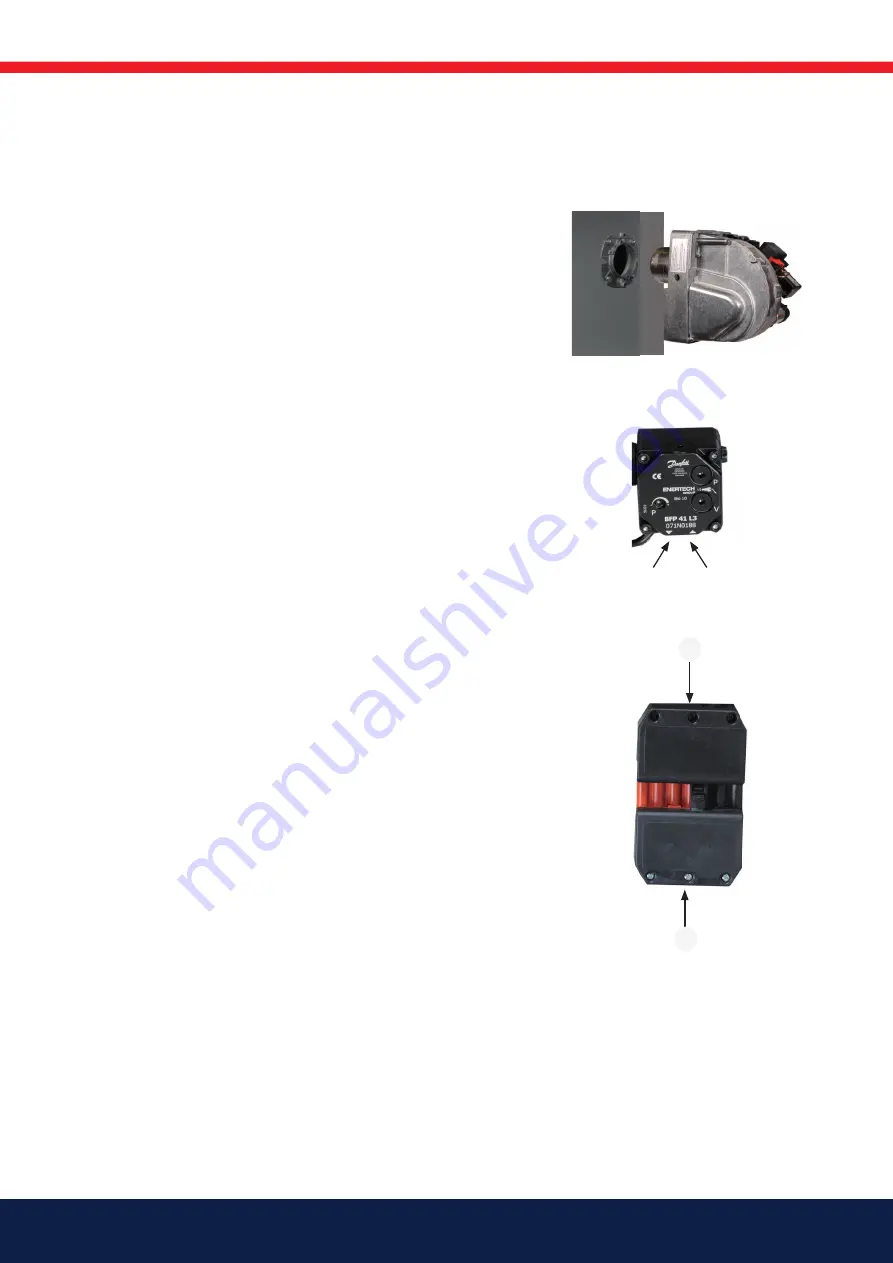
Make sure the hole pattern on the burner corr
esponds to the supplied fl ange
(refer to Technical data).
3.6.2 Burner installation
1.
Install the fl ange with gasket on the boiler.
2.
Fit the selected nozzle
(refer to Technical data).
3.
Install the brake plate and check the ignition electrodes
(refer to Burner Servicing).
4.
Mount the burner to the fl ange.
5.
Insulate between the burner and boiler door to reduce radiated heat (if
necessary).
3.6.3 Oil lines
1.
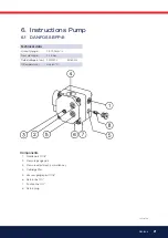
Check the dimensions of the oil lines (refer to Pump instructions).
2.
The oil fi lter should be fi tted to the incoming oil line. If a degasser is
installed, the oil fi lter should be fi tted to the oil line up to the degasser
in order to prolong the service life of the oil fi lter.
3.
For single pipe systems, the return plug must be removed
(refer to Pump instructions).
4.
When installing oil hoses, check that the supply and return hoses are
fi tted to the appropriate connection on the oil pump. The hoses must
be located so that they do not bend or become subject to tensile load.
5.
Bleed the oil system. Dry running will damage the oil pump.
6.
The vacuum in the suction line should not fall below 0,3 bar during
start-up.
3.6.4 Electrical connection
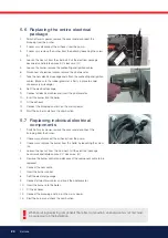
If the boiler does not have a pre-fi tted connector, connect to the supplied
connectors (x2) as shown in the wiring diagram.
1.
Switch off the main switch.
2.
Connect the Europlugs (x2) as shown in the wiring diagram.
3.
Fit the Europlugs (x2) to the burner.
4.
Turn on the main switch.
3.6.5 Check oil line seals
Once the burner has been installed and commissioned, the seals of the
various coupling elements should be checked.
When a leak is detected, it is usually suffi cient to tighten the coupling
element that is leaking.
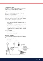
Return
Supply
X1
X2
Содержание B 1 FUV 63-16
Страница 31: ...171 905 28 ...
Страница 34: ......
Страница 35: ......
Страница 36: ...Enertech AB P O Box 309 SE 341 26 Ljungby www bentone se www bentone com ...


