03/ 2011
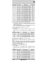
BENNING MM 11
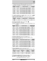
25
200 kHz
10 Hz
± (0.01 % of the measured value + 10 Digit)
0,5 V
SS
1 MHz
100 Hz
± (0.01 % of the measured value + 10 Digit)
0,5 V
SS
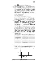
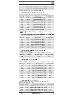
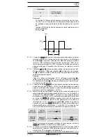
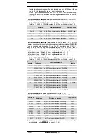
7.10 Pulse duty ratio
(Switch setting: %DF)
Overload protection in the case of pulse ratio measurement: 600 V
eff
Meas. range Resolution Meas. precision Frequency range
Min. sensitivity
20 % ~ 50 %
0,1 %
± 1 %
20 Hz ~ 10 kHz
5 V
SS
50 % ~ 80 %
0,1 %
± 2 %
20 Hz ~ 10 kHz
5 V
SS
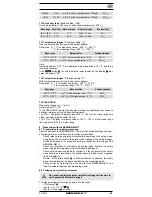
7.11 Temperature ranges °C
(Switch setting: °C)
With temperature sensor type K and sensor adapter
Resolution: 0.1 °C for measuring range: - 200 °C ~ 400 °C
1 °C for measuring range: 400 °C ~ 1200 °C
Meas. range
Meas. precision
Overload protection
- 200 °C
~ 100 °C
± (0,1 %
of the measured value
+ 6 °C)
600 V
eff
100 °C ~ 1200 °C
± (0,1 %
of the measured value
+ 3 °C)
600 V
eff
Note:
Indicated values < 360 °C are displayed with a resolution of 0.1 °C due to an
improved precision.
If the
-button
is used to select a lower resolution, the display
indi-
cates the symbol ”Er”.
7.12 Temperature ranges °F
(Switch setting: °F)
With temperature sensor type K and sensor adapter
Resolution: 0.1 °F for measuring range: - 328 °F ~ 753 °F
1 °F for measuring range: 753 °F ~ 2192 °F
Meas. range
Meas. precision
Overload protection
- 328 °F ~ 212 °F
± (0.1 % of the measured value + 12 °F)
600 V
eff
212 °F ~ 2192 °F
± (0.1 % of the measured value + 6 °F)
600 V
eff
7.13 PEAK HOLD
Measuring ranges: mV, V, mA, A
Coupling type: AC, DC
In the PEAK-HOLD function (peak value storage) an additional error needs to
be taken into account for the specified precision.
+ [± 0.7% + 20 digits] for display values of 20 % - 100 % of the meas. range limit
value, minimum impulse width: 0.5 ms,
+ [± 0.7% + 30 digits], for display values of 50 % - 100 % of the meas. range
limit value within the 2 V meas. range,
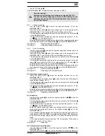
8. Measuring with the BENNING MM 11
8.1 Preparations for making measuring
Operate and store the BENNING MM 11 only at the specified storage and oper-
ating temperatures conditions. Avoid continuous insulation.
-
Check rated voltage and rated current details specified on the safety meas-
uring leads. The nominal voltage and current ratings of the safety measur-
ing leads included in the scope of delivery correspond to the ratings of the
BENNING MM 11.
- Check the insulation of the safety measuring leads. Discard the safety
measuring leads immediately if the insulation is damaged.
- Check safety measuring leads for continuity. If the conductor in the safety
measuring lead is interrupted, the safety measuring lead must be quaran-
tined immediately.
- Before - at the rotary switch
- a different function is selected, the safety
measuring leads must be disconnected from the measuring point.
- Strong sources of interference in the vicinity of the BENNING MM 11 can
lead to unstable readings and measuring errors.
8.2 Voltage and current measurement
Do not exceed the maximum permitted voltage with respect to
earth potential! Electrical danger!
The highest voltage which may be applied to the jacks,
- COM socket
- jack for V,
, Hz, °C,
- jack for mA range
and the

