


Bennett 621 Interconnection Box Instruction & Service Manual
Product Introduction
5
CONNECTOR DESCRIPTIONS
The following is a description of the connections, LED’s, and jumpers located on the 621 circuit board.
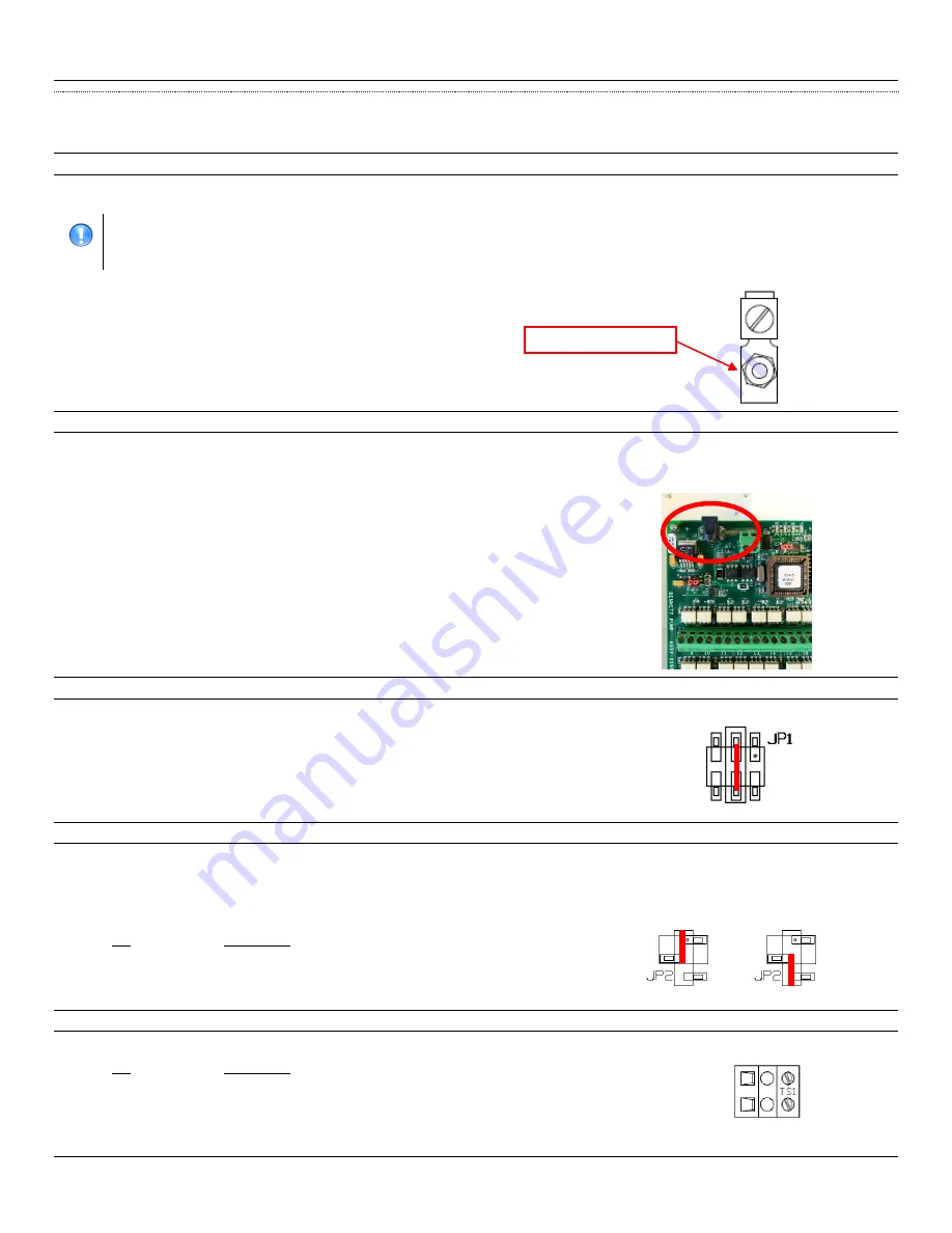
GROUNDING
A 12 AWG green earth ground wire must be connected to the green ground screw inside the enclosure. The green ground screw MUST BE within 1
Ohm of earth ground. This is located near the Fan Out Board.
IMPORTANT
:
Follow proper grounding procedures to reduce radio frequency interference (RFI). All Bennett equipment must be
properly grounded. Follow National Electrical Code, Article 514-7 for grounding requirements as well as Bennett’s
grounding procedures. It is
UNACCEPTABLE
to rely on the conduit for these grounding requirements.
J1
AC LINE VOLTAGE INPUT
The AC Power Module is used to provide AC power to the 621 board at the J1 connector. Only one dispenser electronics Hot and Neutral needs to
be pulled per dispenser.
Each 621 Interconnection Box uses one 120V, 50/60 Hz, or 240V, 50/60 Hz circuit for power. Make sure the power source has the correct frequency
and voltage
JP1
CURRENT LOOP VOLTAGE
The JP1 is a 3-pin jumper used for current loop voltage. The center two pins
MUST
be set for operation in the field.
Note:
Failure to set jumper in
the center position will result in improper operation of the 621 board.
JP2
RUN MODE OR PROGRAM MODE
The JP2 is a 3-pin jumper used to select run mode for field operation or program mode for flash programming (BENNETT USE ONLY).
Run Mode
– This mode MUST be used for operation in the field.
Program Mode
– This mode is exclusively used for flash programming at Bennett Pump Company.
DO NOT CHANGE THIS SETTING!
The board will
not operate correctly if the jumper is in this position.NOT FOR FIELD USE!
Pin
Description
1 & 2 (top)
Run Mode – Field Use Only
2 & 3 (bottom)
Program Mode– Bennett Use Only
TS1
POS COMMUNICATION
Terminal strip TS1 connects to the data distribution cabinet. There is a (+) positive and (–) negative connection.
Pin
Description
1 (orange)
(+) Positive
2 (yellow)
(-) Negative
OR
5 1
6
2
(+ Positive)
(- Negative)
GROUND SCREW
Содержание 104080
Страница 16: ...Bennett 621 Interconnection Box Instruction Service Manual Installation Instructions 12 CONNECTION DIAGRAM...
Страница 20: ...Bennett 621 Interconnection Box Instruction Service Manual Parts 16 Page Intentionally Left Blank...
Страница 21: ...Bennett 621 Interconnection Box Instruction Service Manual Bennett Limited Warranty...


