Bennett 621 Interconnection Box Instruction & Service Manual
Installation Instructions
10
AC POWER WIRING
WARNING:
ABSOLUTELY NO DAISY CHAINING COMMUNICATION DATA WIRES, ORANGE AND YELLOW 18AWG. DAMAGE TO THE
CONTROL CONSOLE MAY RESULT.
WARNING:
MAKE SURE THE 621 INTERCONNECTION BOX IS PROPERLY GROUNDED WITH 12AWG GREEN EARTH GROUND WIRE IS
CONNECTED TO THE GREEN GROUND SCREW INSIDE THE ENCLOSURE. FAILURE TO PROPERLY GROUND THE
EQUIPMENT CAN CAUSE INJURY OR DAMAGE TO THE EQUIPMENT AND WILL VOID THE BENNETT LIMITED WARRANTY.
Follow proper grounding procedures to reduce radio frequency interference (RFI). All Bennett equipment must be properly grounded. Follow
National Electrical Code, Article 514-7 for grounding requirements as well as Bennett’s grounding procedures. It is
UNACCEPTABLE
to rely on the
conduit for these grounding requirements.
1.
A 12 AWG green earth ground wire must be connected to the green ground screw inside the enclosure. The green ground screw
MUST BE
within 1 Ohm of earth ground. This is located near the AC power terminal.
2.
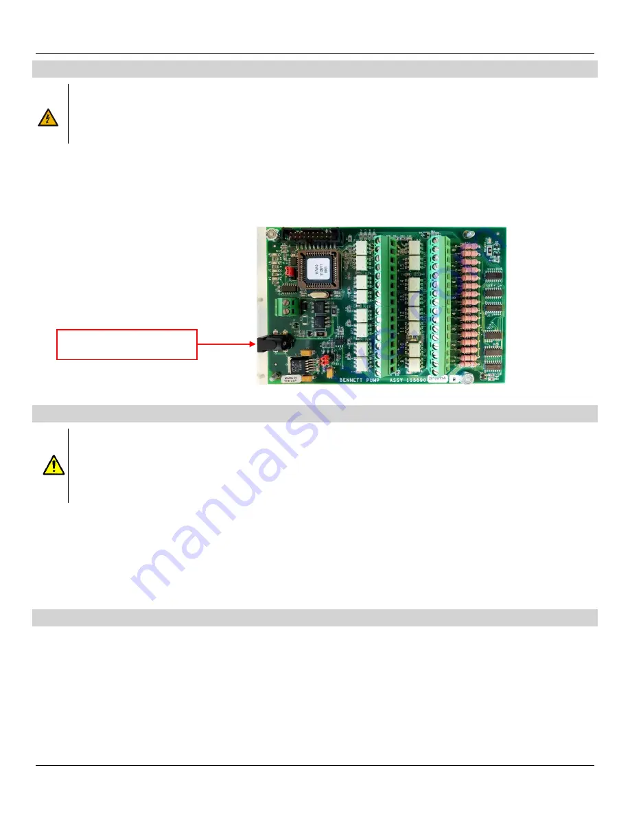
Connect the AC Power Module to J1.
HOW TO CONNECT DISPENSER FUEL COMMUNICATION W IRES
CAUTION:
All communication wires must be 18 AWG or larger gas and oil resistant stranded copper THHN per National Electrical
Code.
CAUTION:
Absolutely no daisy chaining (orange and yellow 18-AWG) communication data wires. Damage to the control console
may result.
CAUTION:
DO NOT use wire nuts. Splicing with wire nuts can cause communication failure, system failure, and may void
warranty.
Dispenser fuel communication wires for fueling positions 1 through 24 terminate directly to the 621 Circuit Board. Each fueling point has a positive
(orange) and negative (yellow) connection. A Fueling Point is one side of a dispenser. A two-sided dispenser would have two fueling points. Each
fueling position is labeled on the circuit board as shown in the figure below. Fueling points 1 through 16 are labeld as 1 through 8. Fueling points 17
through 24 are labeld as 9-12. (e.g. Fueling point 1 & 2 are labeled as 1, fueling point 3 & 4 are labeled as 2 and etc. Refer to the
621 Wiring
Diagram (P2915)
for detailed information.
1.
Connect data wires to terminal strip positions 1-12.
Note:
Each terminal strip channel will supply two fueling positions. This will allow a
maximum of 24 fueling points.
2.
Connect the other end of the data wire to the 708 CPU Board or to the Current Loop Personality Module located on the 819/919 CPU Board.
CONNECT DATA DISTRIBUTION BO X COMMUNICATION WIRES
The following description is used to connect a Data Distribution Box via Generic Current Loop communication. Field connections will depend on the
generic current loop equipment available at the site.
Note:
For any other POS that communicates using Bennett protocol must be programmed on
Channel 1. Refer to the
621 Wiring Diagram
(P2915) for detailed information.
1.
Connect 1 x 18ga. Orange (+ positive) wire to the 621 CPU Board at TS1, + positive as indicated on the diagram. Connect the other end to the
Data Distribution Box.
2.
Connect 1 x 18ga. Yellow (- negative) wire to the 621 CPU Board at TS1, - negative as indicated on the diagram. Connect the other end to the
Data Distribution Box.
INCOMING 12VDC VOLTAGE
Содержание 104080
Страница 16: ...Bennett 621 Interconnection Box Instruction Service Manual Installation Instructions 12 CONNECTION DIAGRAM...
Страница 20: ...Bennett 621 Interconnection Box Instruction Service Manual Parts 16 Page Intentionally Left Blank...
Страница 21: ...Bennett 621 Interconnection Box Instruction Service Manual Bennett Limited Warranty...


